This thread has been locked.

If you have a related question, please click the "Ask a related question" button in the top right corner. The newly created question will be automatically linked to this question.

CAN Termination

Hi ,

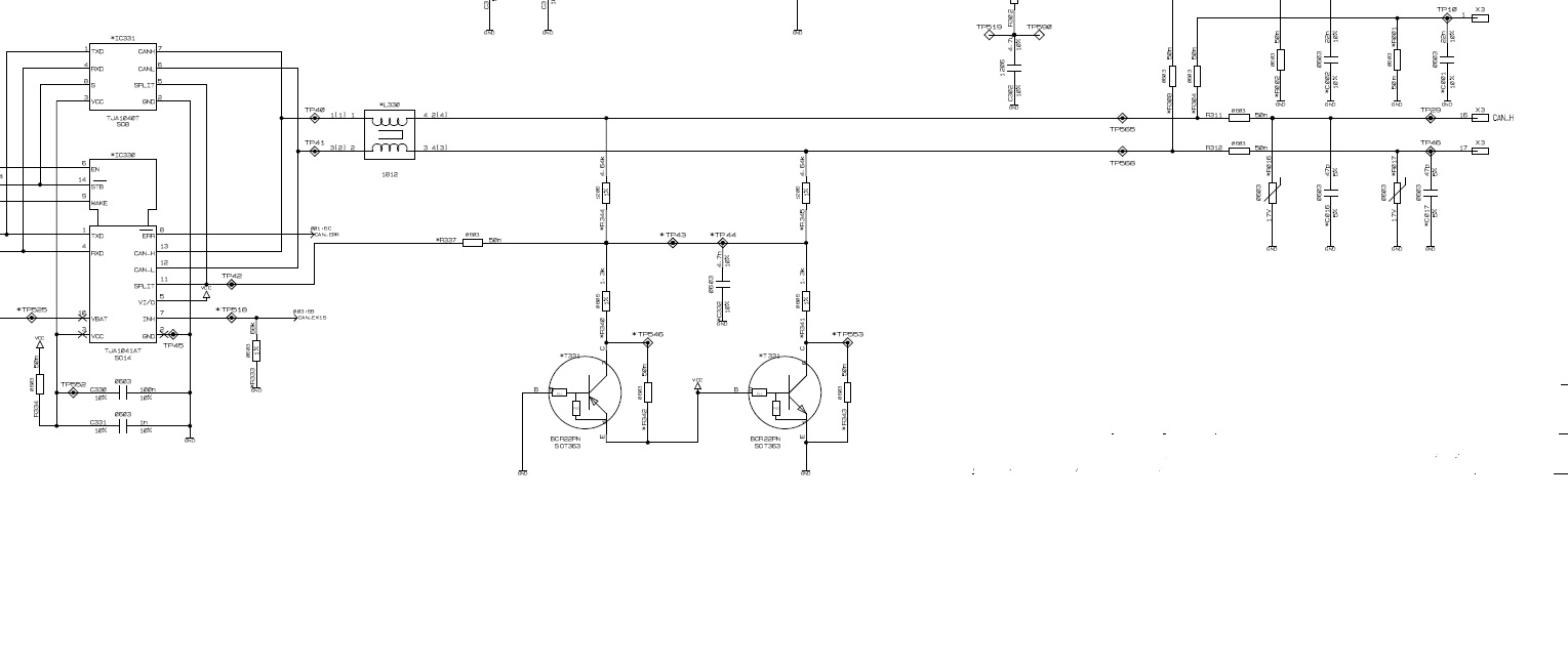
In the attached schematic we can see that two BJT's are connected to CANH and CANL lines. I did not understand why they did so. Can anyone please explain the functions of those two BJT's.

Regards

Hari

  • Hi Hari,

    You should probably check with the person or company who created the schematic to be absolutely sure of the intent behind these components. It doesn't look like this came from TI. My guess is that this circuitry is intended to produce a reference voltage equal to half of VCC in order to more strongly bias the CAN bus's recessive level. This could help to reduce common-mode noise on the bus. This is a similar function to the CAN transceivers' "SPLIT" output pin which is also connected to the same common-mode net on the schematic.

    Regards,
    Max
  • Hi Max,

    Thank you very much for your time and concern. One more doubt ,for generating half of Vcc no need of that two BJT's, correct me if I am wrong.

    Could you please explain the role of those two BJT's and also how strongly biasing reduces the common mode noise on the bus.

    Thanks&regards

    Hari

  • You are right that the two BJTs are not needed. The SPLIT pin connection alone is sufficient to bias the common mode. I wouldn't recommend using the BJTs since this adds complexity without much benefit. You may want to check with the original author of the schematic to see if there was a specific issue they were trying to address.

    Max
  • Thanks Maz, I will check it