This thread has been locked.

If you have a related question, please click the "Ask a related question" button in the top right corner. The newly created question will be automatically linked to this question.

TI TUSB7340 power consumption

Other Parts Discussed in Thread: TUSB7340

The datasheet indicates that we

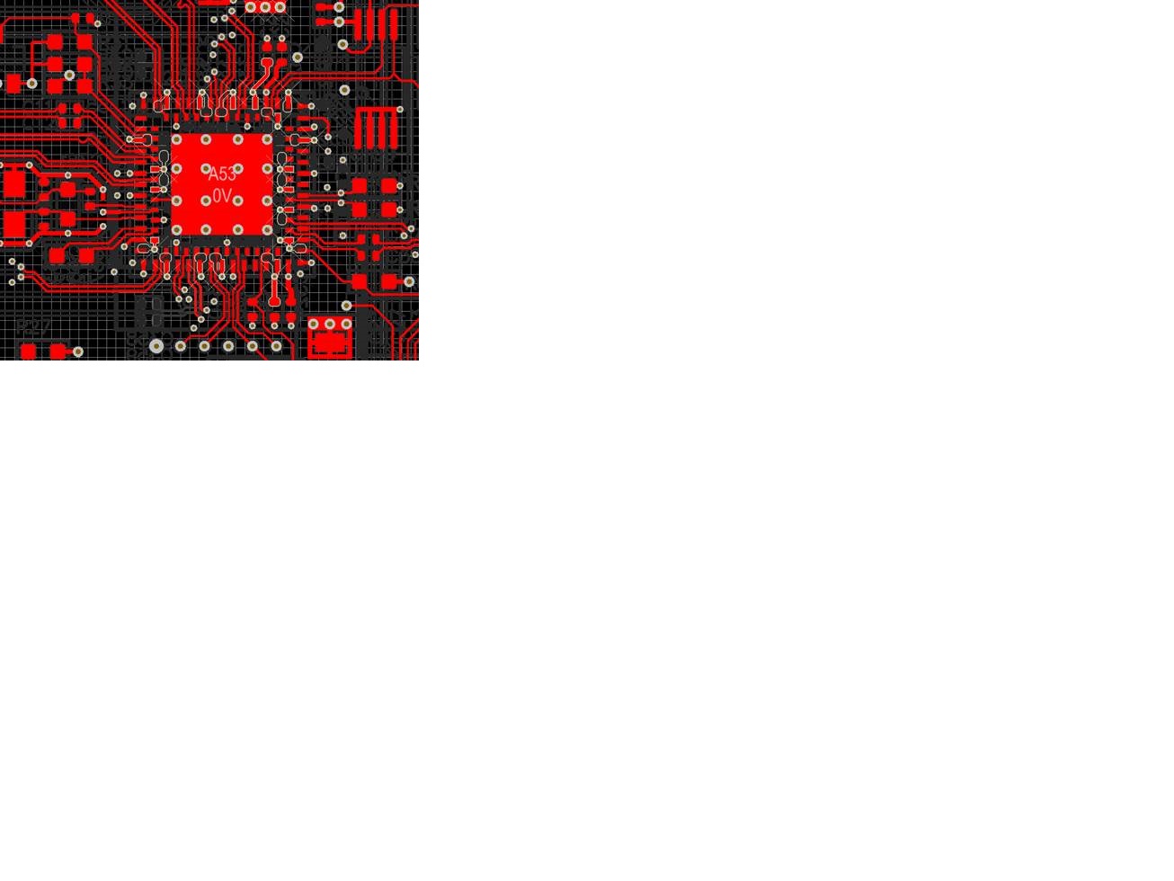
should expect ~80mW during idle, with the system on but no USB devices attached. While we can't accurately measure the power consumption of the chip in-circuit on our design, it would seem that the power consumption is much greater than this. The chip gets very warm in ambient operation (i.e. 50degC) and the local PCB area around it is also elevated, without any USB device attached.

Am I reading/interpreting the consumption figures incorrectly?

I'd expect that 70mW would generate a rise of around 1degC to the PCB at 70mW (15.2degC/W Junction to board). This doesn't fit with what we see.

I'm sure that I've followed the recommendations for layout. I have an 8-layer board with GND attached to 3 dedicated planes, so heatsinking shouldn't be an issue.
 
 
Schematic can be emailed to a TI employee  for your reference. It's possible that I've wired it up incorrectly - we're still in prototyping (beta).

  • Hello,
    We would need to know how much current is the TUSB7340 draining.
    50degC doesn't seem to high to me for junction temperature, how are you measuring the temperature?
    How does it change when there are USB devices working?
    I will contact you by email so you can share your schematics.
    Regards
  • We're measuring the temperature a couple of ways:

    a) using a thermal IR probe pointed at the surface of the TUSB7340. We've then moved the probe away from the TUSB7340 and seen the temperature reduce as we move away from the IC in any direction. This is without any USB devices attached, but the PCIe enumerated - a condition that the datasheet claims a 70mW consumption on (idle with no USB attached). Attaching a USB2 device does not change the temperature noticeably.

    b) using a thermocouple attached to a multimeter. Measuring the surface of the processor (quad-core ARM CPU), the TUSB7340 and the surface of the PCB around both parts, the TUSB case is hotter than the CPU, the PCB area around the TUSB is hotter than the area around the CPU.

    The question still stands:
    At idle the datasheet quotes a consumption of 70mW. I'd expect that 70mW would generate a rise of around 1degC to the PCB at 70mW (15.2degC/W Junction to board). This doesn't fit with what we see. Is this an error in the datasheet or are we misinterpreting what is written?

    It's not easy for us to measure the 1.1V core on our board as it is plumbed straight into a power plane.

  • Hello,
    Sorry for the delay, I've got this feedback from my Technical chief:

    "There could be many reasons it is not in the idle 70mW state. By the fact that temperature measurements indicate it is hot it is probably drawing more that 70mW. So the question is why is it not in the low power state instead of why is it drawing more than 70mW in idle state as in datasheet.

    There is a very narrow condition that the device will draw 70mW. We need to make sure they are in that state."

    How do you know the device is in the idle state?