This thread has been locked.

If you have a related question, please click the "Ask a related question" button in the top right corner. The newly created question will be automatically linked to this question.

DS91M040 Waveform distortion

Other Parts Discussed in Thread: DS91M040

Hi,

We are evaluating the DS91M040 device.

It meets the 3.8V of the recommended input range of the receiver,

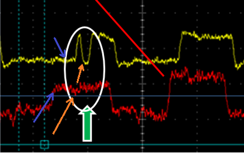
but there is a distortion in the received waveform.

Please see the attached file.

DS91M040.pptx

Is there something that is considered to be the cause of that?

Best regards,
Seishin

  • Seishin,

    The common mode noise on the input waveform is quiet severe.  At the point of "failure" the blue and purple signals are roughly 0mV differential.  This is a difficult condition and does not meet the minimum input criteria for a valid stable output.  Have you tried to change the state of FSEN pins to shift the input threshold voltage?

    Regards,

    Lee

  • Dear Lee,

    Thank you very much for your reply.

    I will investigate the cause of the common mode noise.

    Best regards,
    Seishin

  • Hello,

    Please allow me to ask some questions again.

    The state of FSEN pin does not change. We are using this pin with a Low (TYPE1).

    Please see the attached file.

    DS91M040_Re.pptx

    If the difference between the blue and purple 0mV, red would be the same as the yellow 0mV.

    What do you think about the difference between the two?

    Best regards,

    Seishin

  • Seishin,

    The FSEN pin is an input.  Changing this input to enable a TYPE2 input may help the device response.

    I have tried to add some detail of your waveform in the attachment.  The horizontal Blue line is approximately 0mV differential input for the RED math function.  The lower PURPLE arrow shows an input edge.  There is not enough amplitude on this edge to produce a corresponding response on the M040 output (see the uppper PURPLE arrow).  Eventually the M040 does see enough voltage difference on the input to respond with an output "high".  Almost immediately the input amplitude decreases to ~ 0 mv (see lower ORANGE arrow).  After an internal propagation delay of the M040 this 0mV differential produces a "low" output (see upper ORANGE arrow).

    I hope this helps explain the M040 response to the input waveform.

    Regards,

    Lee