This thread has been locked.

If you have a related question, please click the "Ask a related question" button in the top right corner. The newly created question will be automatically linked to this question.

LMH1983 148.35MHz clock not stable with 720p60 reference

Other Parts Discussed in Thread: LMH1983, LMH1981

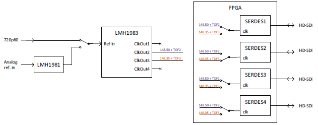
When I genlock the LMH1983 to a 720p60 reference signal, every 1000 frames (about 16.66ms) the clock period of the 148.35MHz clock has a clock period that is too short, sometimes more than 1ns too short. As a result sometimes the PLL in the FPGA loses its lock.

Is there anything I can do in the register settings to prevent these narrow clocks?

Regards,

Henri Faber

  • Hi Henri,

    LMH1983 uses 27MHz to generate the VCO frequency and then this gets divided down to generate 148.5MHz and 148.35MHz clcoks. 148.5MHz clock is an integer number of the VCO(148/27 = 5.5). On the other hand, 148.35/27 = 5.49444.......

    PLL2 is used for integer numbers of frames per second(for example 60 frames per second). On the other hand 148.35MHz clock is used for fractional or divide by 1.001 frame format like 59.94 fps. You are seeing every 1000 this occurs. This comes from the fact to get for example 59.94 we have to count down the 60 fps by 1000. That is 59.94=(60*1000)/1001. On the other hand we have to count down 59.94 fps by 1001 in order to get 60 fps. 60=(59.94*1001)/1000. In summary every 1000 60 fps there is alignment with 1001 59.94 fps. To get this alignment, we have to shorten the clock like what you are seeing. So what you are seeing is normal. However, i was not expecting FPGA to go out of lock since i was expecting it would look at multiple clocks before deciding to declare loss of lock.

    Regards,,nasser
  • Hello Nasser,

    That is what I expected was happening. But I also expect that a PLL can smooth out the difference. This looks more like the behaviour of an NCO than a PLL.

    I have measured the output of the LMH1983. 1000 frames after initialization, which includes a soft reset and a temporary disable of PLL3, I see a clock period that is sometimes more than 2.5ns shorter than the expected 6.74ns. This will always result in a loss of lock. After that I see clock periods every 1000 frames that are mostly about 0.5ns or 0.7ns, which is OK for the FPGA.
    But occasionaly I see a clock period that is 1ns shorter. The reference clock maximum cycle to cycle jitter of the PLL in the FPGA is 0.15UI which is 1.01ns for the 148.35MHz clock. The shorter clock period is getting very close to the limit of the FPGA PLL. Only a little extra jitter cause by temperature or power variations can cause the jitter to be too much.

    Is there a limit to the clock width variation caused by the correction?
    Can the same thing happen to the 148.5MHz clock when a fractional reference signal is used?
    Is there a register setting in the LMH1983 that can limit the clock correction, or spread it over multiple clock cycles?

    Best Regards,

    Henri
  • Hi Henri,

    What you are seeing is expected as long as TOF1 Align Mode is set for Always Align. LMH1983 is trying to always align and the only time this could be done is after 1000 frames. However, this has not been characterized since this could be application dependent.

    If you don't want to see this change in clock period please select never align by setting reg 0x11[5:4] = b11. In this mode, incoming VSYNC and LMH1983 TOF1 are in alignment. Even if incoming VSYNC drifts the LMH1983 TOF1 moves as well. Additionally you may want to crash lock as well by setting reg 0x11[3:2]=b10. This way we lock fast right at the beginning.

    Regards,,nasser
  • Hello Nasser,


    I can get the narrow pulses on the PLL3 clock output to disappear when I set the TOF3 Align Mode to Never Align. We use crash lock for initial locking after reset and then change to drift lock.

    I have received a document from my customer in which he describes the system and asks a couple of questions. I will reproduce it below.

    Our product is a PCI Express based quad port HD-SDI input + output adapter. Each port can be configured to behave as either input or output. The board relies on the LHM1983 to generate all clocks needed for the serializers and de-serializers (i.e. 148.50MHz and 148.35). In a genlock scenario the board also uses the TOF signals to align its outputs to the genlock reference source.
    The following diagram show the general clocking structure.

    The LMH1983 can get its reference from two possible sources, namely: (1) an external analog reference via an LHM1981 sync separator or (2) from an onboard generated 720p60 reference. Each SERDES can either use the output from PLL2 (for non-fractional formats) or PLL3 (for fractional
    formats).
    There are three general usage scenarios, namely:

    1. No Genlocking, which means the onboard 720p60 reference source is selected. In this mode we want PLL2 to generate a stable 148.5MHz and TOF2 should generate a non-fractional frame rate (as defined by the PLL2 format setting).
    PLL3 should generate a stable 148.35MHz and TOF 3 should generate a fractional frame rate (as defined by the PLL3 format setting).
    Both PLLs do not have to align to the 720p60 reference.
    Until now we have set the TOF alignment for all PLLs to auto, but it is our understanding now that in this scenario it is better to set alignment to never align.

    2. An external non-fractional analog reference is connected, which mean the LMH1983 will be setup to use the reference signal from the LMH1981. In this case we want PLL2 to lock and align to the non-fractional reference.
    PLL3 should generate a stable 148.35MHz and TOF3 with the framerate set by the PLL3 format setting, however it does not have to align to the non-fractional reference.
    Until now we have set the TOF alignment for all PLLs to auto, but it is our understanding now that in this scenario it is better to set PLL2 alignment to auto (or always?) and PLL3 alignment to never.

    3. An external fractional analog reference is connected, which mean the LMH1983 will be setup to use the reference signal from the LMH1981. In this case we want PLL3 to lock and align to the fractional reference.
    PLL2 should generate a stable 148.50MHz and TOF2 with the framerate set by the PLL2 format setting, however it does not have to align to the fractional reference.
    Until now we have set the TOF alignment for all PLLs to auto, but it is our understanding now that in this scenario it is better to set PLL3 alignment to auto (or always?) and PLL2 alignment to never.

    NOTE: in all of the above scenarios PLL1 is set to auto align and PLL4 is not used and left to its default settings.

    Our questions for you are:
    1. Is our understanding correct that if we want a glitch free clock and have no need for alignment we should set the TOF alignment mode to never?
    2. Can the LMH1983 generate a TOF with at a stable interval (set by PLL format) with alignment mode set to never?
    3. Can the LMH1983 create correct TOF pulses when a progressive reference signal is connected (Fin does not toggle in case of a progressive)??
    4. Does the alignment setting of PLL2 have any effect to PLL3 behavior and vice versa?
    5. Do the settings of PLL4 mater if we are not using its clock output at all?

    Regards,

    Henri

  • Hi Henri,

    Just wanted to let you know ahead of time that Nasser is out of the country on business travel this week, so E2E responses for this thread will be delayed during this time. We will try to get back to you with a response as soon as possible, and apologies for the inconvenience.

    Regards,

    Michael
  • Hi Henri,

    Before my travel, i noted your questions.

    First of all, thanks for detailed explanation of your overall setup. Please below note responses to your questions.

    1. Is our understanding correct that if we want a glitch free clock and have no need for alignment we should set the TOF alignment mode to never? *NM: Your understanding is correct. I don't call this glitch but call this duty cycle correction between integer vs fractional format conversion in always align mode.

    2. Can the LMH1983 generate a TOF with at a stable interval (set by PLL format) with alignment mode set to never? *NM: Yes
    3. Can the LMH1983 create correct TOF pulses when a progressive reference signal is connected (Fin does not toggle in case of a progressive)?? *NM: Yes we have used Tek TG700 and verified this.
    4. Does the alignment setting of PLL2 have any effect to PLL3 behavior and vice versa? *NM: PLL2 and PLL3 are independent but both use 27MHz PLL1 to genlock to.
    5. Do the settings of PLL4 mater if we are not using its clock output at all?*NM: It does not. I suggest to disable it.

    Regards,,nasser

  • Hello Nasser,

    Thank you for your answers. They have helped us very much.

    Have a good trip.

    Best Regards,

    Henri