This thread has been locked.

If you have a related question, please click the "Ask a related question" button in the top right corner. The newly created question will be automatically linked to this question.

ISO3086 Max Load Test

Other Parts Discussed in Thread: ISO3086

Hi,

Ref: Technical Document  "RS-485 failsafe biasing: Old versus new transceivers" from TI.

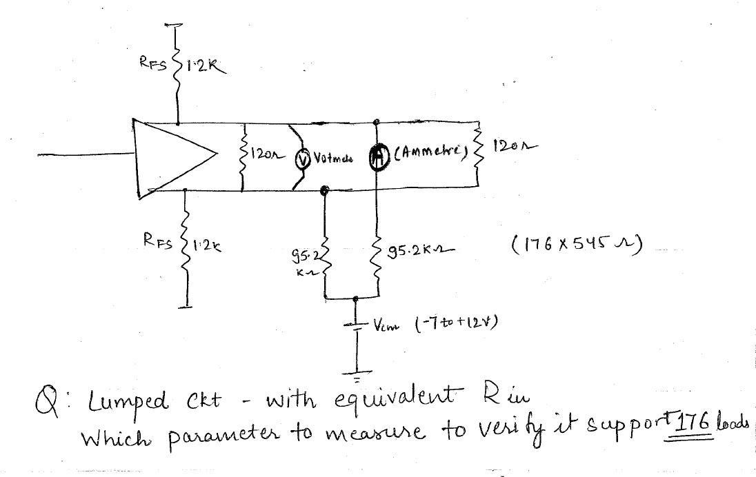
In the attached file Figure 1 RS485 (ISO3086) configuration on my board. Rfs are fail safe resistors. I calculated the max slaves that can be added by the above reference.

In Figure 2 - Used a common mode loading circuit for verification. (Ref: ISO3086 Datasheet Figure 3). 

Q: How do I verify practicaly the calculated value of maximum number of loads. (ie Test Circuit? Value to look for?).

ISO3086_Max Load.pdf

Siddharth Gupta

  • Q: How do I verify practicaly the calculated value of maximum number of loads\slaves that can be added to ISO3086 when fail safe is applied?

  • Please refer to the next post for calculations and the answer.

  • Hi Rao,  

    Thanks for replying.

    Rin = 545 Ohm

    So equivalent Rin (for 176 Loads) = 176*545 Ohm = 95.92 K Ohm.

    Q: How do I verify My configuration supports 176 Loads?? (what parameters do I need to measure and verify??)

    Regards,

    Siddharth Gupta

  • Hi Siddharth,

    Please ignore my earlier post and refer this post for calculations. For a failsafe biased RS-485 network, the design process involves calculating RFS, RT1 and nL in the order stated.

    To calculate RFS, use Equation 6 of the White Paper "RS-485 Failsafe Biasing". For device ISO3086, VS(min) is 4.5V, VAB(min) is -10mV and we can assume Z0 to be 120Ω, 50mV noise margin for VAB(min) making it 40mV. With these, you will get RFS as 3.15kΩ.

    RT1 can be calculated using Equation 4. In this case, RT1 is calculated to be 122Ω.

    To calculate the maximum number of transceivers that can be connected on the bus is use Equation 7. This equation uses a parameter called Unit Load (UL) where a standard UL is considered to be 12kΩ. Since ISO3086 has a value of RID & RIN = RID/2, UL = 12kΩ/RIN = 1/2. Using Equation 7, we get n <= 56 transceivers.

    To verify your configuration supports 56 devices, you can setup lumped equivalent circuit as shown in Figure 4 of the white paper for which we have calculated RFS and RT1. RT2 was assumed to be Z0 (120Ω) and RINEQ can be calculated as 429Ω using Equation 2. RINEQ is basically the equivalent resistance of 'n' transceivers connected in parallel, hence RINEQ = RIN/n.

    After the above setup is done, you can monitor the differential output across RT2 for verification. Upto 56 transceivers (or RINEQ = 429Ω), you would see Differential Output complying VIT(+) and VIT(-). When you connect more than 56 transceivers (or RINEQ < 429Ω), Differential Output will start violating VIT(+) and VIT(-). Please note that we have considered a noise margin of 50mV during calculations, hence you could see the setup working for a few transceivers more than 56 transceivers.

    I hope this answers your questions with detailed calculations.

    Best Regards,
    Koteshwar Rao