This thread has been locked.

If you have a related question, please click the "Ask a related question" button in the top right corner. The newly created question will be automatically linked to this question.

DP83867 10Base-T Compliance test

Guru 15520 points
Other Parts Discussed in Thread: DP83867IR

Hi,

I have a question about Ether Compliance Test for DP83867IR.

I'm trying to test 10Base-T "Common Mode Voltage" test with DP83867.
DP83867 are linked-up compulsorily(writing '1' to [PHY Control Register (PHYCR), Bit:10]
and I set the DP83867 to transfer random data by setting BIST register.
But no signal are coming out.

Does DP83867 output random data when it is in 10Base mode?
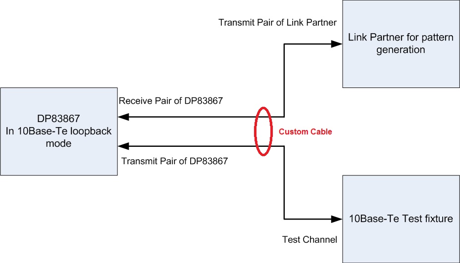
If not, do I need to connect link parter as packet generator and set reverse loopback mode of DP83867?

best regards,
g.f.

  • Hello g.f.,

    Your second approach is the right one. You would need a external random packet generator as a Link Partner (LP) connected to DP83867 in 10base-Te force mode.  Since DP83867 has to be connected to LP and the test fixture at the same time you would need a custom cable assembly. 

    For creating a custom cable assembly, connect transmit pair of LP to Receive pair of DP83867 and Transmit pair of DP83867 to the test fixture. You will have to force 10Base-Te on both DP83867 and the LP. Depending on which pair you would like to act as transmit and receive, you  would also need to select MDI or MDIX mode on DP83867 and LP. DP83867 should also have reverse loopback enabled.

    While making this cable please try to keep the length as short as possible and also connect the ground of the test fixture to the ground of EVM.

    -Regards,

    Aniruddha

  • Hi Aniruddha,

    Thank you for the answer.
    I understood that link parter and custom cable are needed
    for 10BaseT Common mode output voltage test.

    Actually this question was from my customer and
    they have additional question.

    They are using Keysight osciloscope and test fixture(TC4 part).
    This TC4 part have only one RJ45 and BNC connector.
    So, we don't know how to connect DP83867, Link Partner, Test Fixture.
    Can you please show us by block diagram or images?

    And which test fixture should be used?

    best regards,
    g.f.
  • Hello g.f.,

    Please use the following block diagram for reference:

    Looking at the Keysight test manual, TC4 seems to be the right place for Common Mode Voltage test. I checked for Model N5395A and N5395B/C. I would recommend verfiying the model number of the test board and checking in Keysight's Ethernet Test manual.

    As noted in my previous answer, please connect the EVM ground to the Test Fixture ground.

    -Regards,

    Aniruddha

  • Hi Aniruddha,

    Thank you for the answer.

    I'm sorry, but let me ask again to make me sure.

    So, custom cable are required and this is standard for DP83867 10Base-T Common mode output voltage test.
    Why I'm asking this question is because, other 10Base-T PHY will send data without any Link parter.

    best regards,
    g.f.
  • Hello g.f.,

    You are correct, this is a requirement for DP83867 10Base-Te compliance tests. Please note that no custom cable is needed for normal operation. Connecting the  Transmit Pair of Link Partner to the Receive pair of DP83867 allows DP83867 to detect an active Link Partner in 10Base-Te mode. Then DP83867 can generate the test pattern on its own Transmit pair which would be connected to the compliance test fixture.

    -Regards,

    Aniruddha