This thread has been locked.

If you have a related question, please click the "Ask a related question" button in the top right corner. The newly created question will be automatically linked to this question.

PCF8575 : RESET problem

Other Parts Discussed in Thread: PCF8575, TCA9535

Hi all,
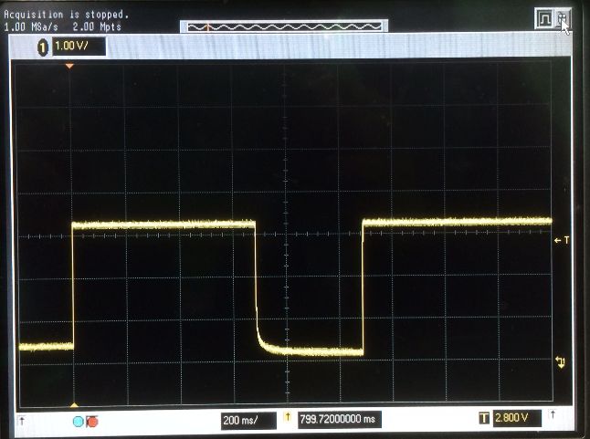
My customer faced a reset problem of PCF8575.

At power on, the I/Os should be high as the datasheet described. But the I/Os is not high by a probability of 70%.
Even if some port is connected to Vcc with a 10k-ohm resister, the level is still low. It seems that the I/Os are set to low.

The test condition is as follows;

1. Vcc=3.3V
2. All I/Os are open
3. INT is open due unused.
4. I2C-CL/I2C-DA pullup to 3.3V with 1kΩ

Could you give me any advice about this phenomenon occurs?

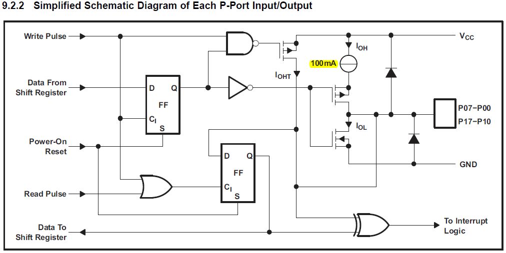
Anyway, I have one question about below block diagram.
When I/Os are high, IOH current source is about 100uA, isn't it?
Because IOH of the electrical specification is -30 to -300uA.
  

Regards,
Toshi

  • Toshi-san,

    I've contacted the correct application engineer for this specific part to respond to your question. While we wait, I'll respond with what I can:

    One question about block diagram: Yes, the current source allows up to 100 uA typical. The -30 to -300 uA is over the full voltage range, and takes process variation into account. This is why the IOH value is bigger than the block diagram.

    If you require an IO expander with stronger pull-ups and more features, I'd suggest looking at the TCA9535

  • Hi Jonathan-san,

    Thanks for your reply.

     I am sorry that the block diagram was not attached.
    According to the below block diagram, IOH is 100mA instead of 100uA.
    Is it a typo?

    I am looking forward to receiving the answer for the first question.
    Anyway, thanks for your kind support. 

    Best regards,
    Toshi

  • Toshi-san,

    You are correct. This is  a typo. It should be 100 uA.

  • Hello Toshi-san,

    My apologies for the delay in response on the first question.
    This is a strange issue that I have not seen before.

    As Jonathan mentioned, there should be a 100uA pullup on each of the outputs on startup.
    Does this happen on initial power up? Or only after a reset?

    Are there particular outputs that display this behavior consistently? Or are you finding that different outputs display this behavior erratically?
    If you change the outputs that seem to be starting up in output low to output high does this problem still persist?
    Is your design dependent upon these outputs starting in the "high" state?

    Best,
    Michael
  • Hi Michael-san,

    Thanks  for your reply.

    This happened on power on/off test. And they expected the I/Os are  input. and I/Os are open.
    So, I/O s should be a high level output. But some times thees level is low.
    I got the Vcc wave form when they did the test.  And I found there is 200mV or 300mV bias
    when Vcc is off.  When this bias is removed or is decreased, the strange issue becomes little.

    However, Vcc is down to the minimum Vporf (0.767V), so I think POR should work well.


    The ramp up time is about 1.4ms and the ramp down time is about 40ms (3.3V to 0.5V).


    Best regards,
    Toshi

  • HI,
    Could you give me any comments on this issue?

    Best regards,
    Toshi
  • Hello Toshi-san,

    My apologies for the delay.
    Do you see that the outputs are low on the initial startup? Or is it only on power-on reset that this happens?
    Are there certain pins that consistently displaying this behavior?

    What bias are you mentioning is 200 to 300mV?
    How are you removing this bias?

    Best,
    Michael
  • Hi Michael-san,

    Thanks for your support

    For checking the I/O status, the 10k-ohm register is connected between Vcc and I/O.
    After Power on, I/O level is low., not high. it seems that the I/O outputs are low.

    About the bias, Vcc is not down to 0V at Power OFF condition when they did the Power ON/OFF test.
    And about 200mV or 300mV is remained at Vcc OFF condition.
    When they did the cold reset from Vcc=0V, the device did the reset correctly.

    I hope that my answer is a help to your question.

    Best regards,
    Toshi
  • Toshi-san,

    Are they able to force Vcc down to 0V instead of 200mV or 300mV during the power on reset?
    If so, does that help to fix the issue or does it still persist?

    When the outputs are low in this error type condition, can they write to all the pins to tell them to go high? If so, do they all get set high or are they stuck in this low output condition?

    My apologies for so many questions, as I have not seen this issue before.

    Best,
    Michael
  • Hi Michael-san,

    They have been checking their designed power supply for removing 200mV during power on reset,
    and need more time for this modification.

    About register, they can write "1" to I/O registers and I/Os go high.
    Currently, they're using this way to evade the problem.

    Best regards,
    Toshi
  • Toshi-san,

    That is good to hear that they can overwrite the low levels. At least it is not stuck in the low level, and they do have a workaround.
    Hopefully being able to remove that 200mV bias should help fix the problem.

    Before the power on reset, are the outputs high? Are the outputs that end up being low after POR in a high state before the power on reset?

    Best,
    Michael
  • Hi Michael-san,

    After writing "1" in I/O registers,
    when POR is carried out in the state with the 200mV -300mV bias in Vcc OFF,
    the output was HIGH and was LOW at random.

    Best regards,
    Toshi
  • Toshi,

    Do you have a schematic and layout that you can provide?
    Can you also provide scope shots of the Vcc in addition to one of the outputs?

    Best,
    Michael