This thread has been locked.

If you have a related question, please click the "Ask a related question" button in the top right corner. The newly created question will be automatically linked to this question.

TPS65982, dead battery and PP_HV EXT activation

Other Parts Discussed in Thread: TPS65982, HD3SS460

Hi,

I am working on the TPS65982 evaluation board for my future design. 

I want to use the dead battery feature.

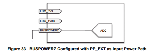
My TPS65982 is configured to not activate the PP_HV EXT path at start up thank to the BUSPOWERZ input (tie to 3V3). Then it configures itself in sink mode and negotiates a voltage of 20V.

This steps are operationals as I can measure with the oscilloscope a 5V on VBUS on startup and then a 20V.

Next I want to use the PP_HV EXT path to power my board. It is configured as SwitchConfig_AS_IN in my configuration file. But the path is never closed.

Is there a bad configuration of my project? To do that I started with the "TPS65982 Upstream-Facing Port Only, supports HD3SS460 Mux:"

  • The TPS65982 has 2 modes of operation: BOOT Mode and APP Mode.

    1. BOOT Mode - FET Path determined by HW settings. When booting up in Dead Battery from VBUS, the Boot code knows that is must be a Sink and determines a FET Path to use as a Sink based on the voltage on BUSPOWERZ read by the ADC.
      1. BUSPOWERZ = LDO_3V3 = 3.3V,       NO FET Path closed in Dead Battery
      2. BUSPOWERZ = LDO_1V8D = 1.8V,    PP_HV Internal FET Path closed as a Sink
      3. BUSPOWERZ = GND = 0V,                   PP_EXT External FET Path closed as a Sink
        1. NOTE: The other 2 HW settings for BUSPOWERZ you do not need are depicted on page 42 of the TPS65982 datasheet

    2. APP Mode - FET Path determine by FW settings after DeadBatteryFlag is cleared. After booting up in Dead Battery from VBUS, the FW setting running in Application Code cannotoverride the HW setting used in BOOT Mode. The following scenarios may occur at this time:
      1. VBUS present since BOOT Mode, VIN_3V3 = don't care  - DeadBatteryFlag = 1 (HW setting is used)
      2. VBUS present since BOOT Mode, VIN_3V3 = 3.3V, 'DBfg' 4CC command sent by EC - DeadBatteryFlag = 0
      3. VIN_3V3 = 3.3V, VBUS removed - DeadBatteryFlag = 0, cleared automatically (FW setting is used now)

    NOTE: DeadBatteryFlag is Bit 2 in BOOT Flags (Reg. 0x2D) in the I2C Host Interface, documented on Page 59 (in Appendix A of the TPS65982 FW User's Guide)

  • As you can see, if BUSPOWERZ = LDO_3V3 in HW, and the system relies on VBUS being connected to PP_EXT in order to power on critical components like Battery Charger & the EC, you are stuck in a situation where the switch is never closed and the system never receives power.

    Therefore, HW FET Settings used in BOOT Mode must match FW FET Settings which eventually take control in APP Mode.
  • Hi Brian,

    Thank you for the answer.
    But I tried the TI software to communicate by I2C, and indeed after the power up I can read the Deadbatteryflag is active.
    I tried to clear the Deadbatteryflag by I2C, byt the FW settings are not used.

    So If I understand this chip cannot be used in a dead battery condition if the electronic need 20V to operate?