


Hello,
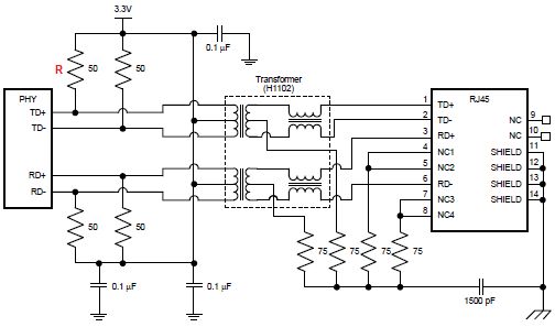
Please, In the application below and for the component DP83848QSQX, how to calculate the power stress of the pull-up resistance R (in RED)
And how to calculate the power stress of the transformer.
Thank you for replaying,
BR,
Abdelmouneim,
Hello,
Please, In the application below and for the component DP83848QSQX, how to calculate the power stress of the pull-up resistance R (in RED)
And how to calculate the power stress of the transformer.
Thank you for replaying,
BR,
Abdelmouneim,

