This thread has been locked.

If you have a related question, please click the "Ask a related question" button in the top right corner. The newly created question will be automatically linked to this question.

AN-1730 DP83640 Synchronous Ethernet Mode

Other Parts Discussed in Thread: DP83640

Hallo,

we have implemented a synchronous repeater using two DP83640 devices and having them connected according to AN-1730 Figure 5 :  

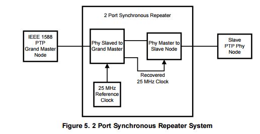
We are a little bit concerned now, because the second PHY uses the recovered, adjustable PTP clock as X1 reference clock . According to the DS of the DP83640 the X1 clock has a tolerance of only +/- 50 ppm. This specification is violated in this setup, because the PTP clock is adjustable within some hundred ppm. Is this a problem? Should we limit the PTP clock adjust rage? If yes, to which value?

Best regards and thank you for your support!

Reto

  • Reto,

    If you are setting SYNC_ENET EN, bit 13 in the PHY Control Register 2 (PHYCR2), Address 0x1C, the output clock will be derived from the recovered receive clock. This clock can be used as the X1 reference clock.

    Patrick
  • Hello Patrick,

    thank you for your reply. In our setup, CLK_OUT is derived from the internal PTP clock. 

    When we adjust the PTP clock frequency to +700ppm for example, then the second PHY stops working. Our question is now: To which value should we limit the PTP clock frequency adjustment or in other words what is the tolerance of the X1 reference clock input?  Test have shown, that the PHY stops working when we adjust the PTP clock more than approx. +/-600 ppm