This thread has been locked.
If you have a related question, please click the "Ask a related question" button in the top right corner. The newly created question will be automatically linked to this question.
Hi,
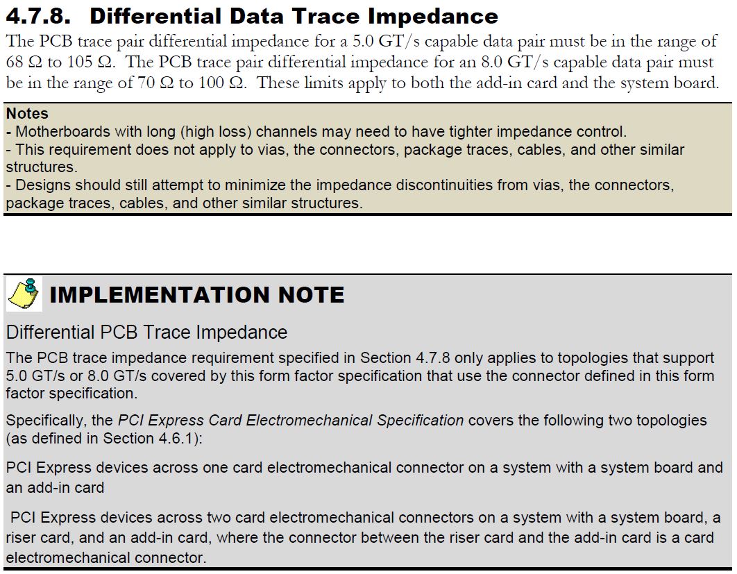
I'm hoping this is a stupid/simple question but here goes. I'm looking at this device DS80PCI102 or similar (possibly the 4 lane) for a PCI Express Gen 2 application. I note that internally it terminates 100Ω differentially and 50Ω singled ended, but my understanding is that for Gen 2 and higher differential routing should be at 85Ω differential, so I would expect the termination to match?
This re-driver will interface with an FPGA where it is possible to configure the termination to 85Ω or 100Ω depending on the application, which ties in with how I would expect a design to work. However the re-driver doesn't have this option.
I don't have access to the PCIe spec currently to check but I thought I would ask the question as to if anyone knows why this is the case?
Thanks,
Alan
Hi Alan,
This is not a stupid question, as we have received this query before, so thanks for bringing it up!
The use of 100-ohm differential resistance internally allows us to interface with most SMA cables and differential trace designs, which are commonly designed to be 100-ohm differential impedance. This goes beyond the scope of PCIe, and this also encompasses designs for IEEE802.3 Ethernet and SAS/SATA protocols, for which we also have internal 100-ohm resistance for those redrivers.
While you are correct that 85-ohm differential impedance is the PCI-SIG recommended impedance for trace routing in PCIe, the PCIe spec actually allows for differential impedance up to 120-ohms without spec violation. I have compiled these specs below, taken from Section 4.3.3.13 (Tx Parameters) and Section 4.3.4.5 (Rx Parameters):
Since the internal 100-ohm termination of the DS80PCI102 cannot be changed, we recommend that you design for only one differential impedance where possible to minimize reflections due to impedance discontinuity. For example, problems arise when you use a 100-ohm connector to interface with 85-ohm differential board trace. However, even if you are forced into a scenario where you use the DS80PCI102 in an 85-ohm differential trace environment, you will still be within the PCIe specification.
I would advise that you can program the termination of your FPGA to 100-ohms and design with 100-ohm differential impedance.
Regards,
Michael
Hi Michael,
Thank you for your reply, very thorough. I didn't appreciate that the specification for the receiver / transmitter was as shown. That basically looks to me reading it that it should be 100 ohm differential / 50 ohm single ended, i.e the device is exactly on specification.
I believe the differential trace impedance requirement comes from the Card Electromechanical spec, and that it has gone from 100 ohm +/-20% for gen 1 down to 85 ohm +/-15% for Gen 2 (and similar for gen 3.) I'm not sure it's exactly that, but around that... I've got that info from the Com Express Module Design guidelines that we have available to us.
I take it this my misunderstanding has come along because the requirement is for a DC differential/single ended impedance, and that at impedance at the transmission rate will be different. Am I right in thinking this is defined by the return loss defined elsewhere in the transmitter / receiver requirements (RLtx-diff & RLrx-diff) as shown in the notes in the image you attached above? This I guess would be tested for a device using an network analyser and SMA connectors with 50R/100R references?
Thanks for your help!
Regards,
Alan.
Hi Alan,
I looked at the Card Electromechanical specification to see if there was resolution with this discrepancy. There appears to be a mix between 85-ohm trace impedance and 100-ohm load impedance. Please see Section 4.7.8 of the CEM spec below:
The two topologies in Section 4.6.1 address PCIe devices placed on the system board (such as a CPU) and add-in cards.
This information appears to be in line with the CEM guidelines you have, as 85-ohms is in the middle of the 70-100 Ohm range. However, most of the tests described in the CEM specifications appear to still be with 85-ohm trace going into 100-ohm differential loads.
I would not expect the differential impedance to change with the transmission rate. If impedance varied with transmission speed, this would make for a host of reflection issues when data transmission frequencies vary based on the length of consecutive 1's and 0's in the bitstream. The differential impedance is defined primarily by the width of the traces, the dielectric material, the height from differential trace to the substrate, the thickness of the trace, and the spacing between the differential pair. A network analyzer will help you identify the amount of insertion loss that results due to transmission from point A to point B as it varies with frequency, so I don't think this necessarily answers your question about the 85-ohm/100-ohm discrepancy.
From what I am seeing in the spec, it seems possible to interface a 100-ohm load with 85-ohm differential impedance traces without spec violation.
Thanks,
Michael
Hi Michael,
Again thanks for coming back quick and thoroughly, sounds like I can route at 85R into these devices and be within spec.
Thanks for your help!
Regards,
Alan.