This thread has been locked.

If you have a related question, please click the "Ask a related question" button in the top right corner. The newly created question will be automatically linked to this question.

DS125BR401A - OOB issue

Other Parts Discussed in Thread: DS125BR401A

Dear Sir 

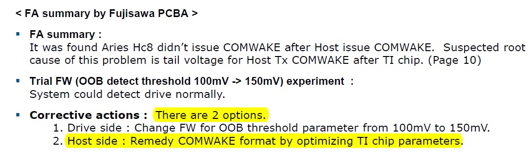
Using TI repeater DS125BR401A for some of HDD will meat detection issue 

So far ,If we change Device side OOB threshold from 100mV to 150mV (HDD can be detected normally)

But ,how could I verify Host side (DS125BR401A) about this issue (no comwake event ) 

  • Hi Kai,

    In port does this signal go through on the DS125BR401A?  The A-port or the B-port?

    It may be possible to change the settings on the DS125BR401A to allow OOB to work without adjusting the detect threshold.

    Regards,

    Lee

  • Dear Lee

    Below is the B side setting ,we test 3 different type of HDD 

    If HGST 8T this HDD change their S/W (OOB detect threshold voltage from 100mV to 150mV) by HDD vendor themselves 

    The detection and Iometer could be workable 

    if HGST 8T not change their S/W and just change DS125BR401A's setting ,The test is fail and the fail setting as below 

    Please kindly help to suggest

  • Hi Kai,

    To make the DS125BR401A adjustment will require SMBus register access (ENSMB=1) or EEPROM configuration (ENSMB = Float).

    Regards,

    Lee

  • Dear Lee

    I don't understand your mean
    So you suggest us to use SMBus mode or EEPROM mode to verify this issue
    If yes ,I have no idea what's different between pin mode and SMBUS mode ,how could I use SMBUS mode to solve this issue
    Do you have recommend value to try ??
  • Kai,

    There several SMBus registers which control the DS125BR401A performance.  Each B-side channel has one register for the signal detect control.  Forcing the signal detect control "on" will change the OOB response of the DS125BR401A.

    Register writes:

    Write Register 0x06 = 18'h  (Enable SMBus control)

    Write Channel B0 Register 0x0D[1] = 1’b (Force signal detect to always be “on” CH B0)
    Write Channel B1 Register 0x14[1] = 1’b (Force signal detect to always be “on” CH B1)
    Write Channel B2 Register 0x1B[1] = 1’b (Force signal detect to always be “on” CH B2)
    Write Channel B3 Register 0x22[1] = 1’b (Force signal detect to always be “on” CH B3)

    Regards,

    Lee 

  • Dear Lee

    Thanks for your reply

    But I can't find the register 0x0D ,0x14 ,0x1B ,0x22 in the datasheet
    Does it hide ??
  • Dear Lee

    So you mean below register 0x0D / 0x14 / 0x1B / 0x22 change from 0x00 to 0x01??

    Thanks

  • Hi Kai,

    Here are the details for each register write.

    Register writes:

    Write Register 0x06 = 18'h  (Enable SMBus control)

    Write Channel B0 Register 0x0D[1] = 1’b (Force signal detect to always be “on” CH B0)
    Write Channel B1 Register 0x14[1] = 1’b (Force signal detect to always be “on” CH B1)
    Write Channel B2 Register 0x1B[1] = 1’b (Force signal detect to always be “on” CH B2)
    Write Channel B3 Register 0x22[1] = 1’b (Force signal detect to always be “on” CH B3)

    Since we are writing into bit "1" in the register [7:0]. Write the following hex values

    0x0D = 02'h       //*  0000 00010

    0x14 = 02'h

    0x1B = 02'h

    0x22 = 02'h

    Regards,

    Lee

  • Hi Lee,
    Is above SMBus setting exist on DS125BR401A EEPROM? thanks
    Best Regards
    Eddie Chou
  • Hi Eddie,

    Registers to control Signal Detect in the previous E2E post do not have a location for EEPROM configuration.  The DS125BR401A OOB response can be improved with another register (it is also hidden in the datasheet).

    With EEPROM configuration I recommend to program SMBus register 0x4C = 01'h  (the default is 00'h)

    This register bit is listed in the datasheet EEPROM map on page 22. I have cutout a part of the table below, the highlighted EEPROM location should be programmed with a 1'b1 for better OOB performance.

    Regards,

    Lee