This thread has been locked.

If you have a related question, please click the "Ask a related question" button in the top right corner. The newly created question will be automatically linked to this question.

DS15BR400 with long cable

Other Parts Discussed in Thread: DS15BR400

Hi,

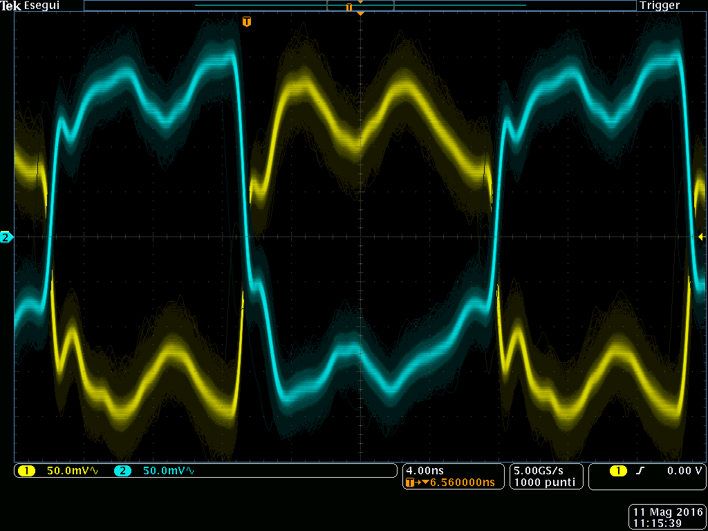
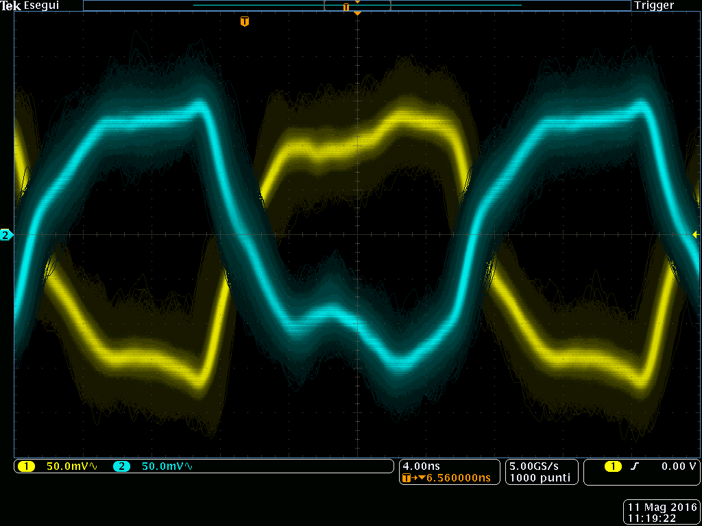
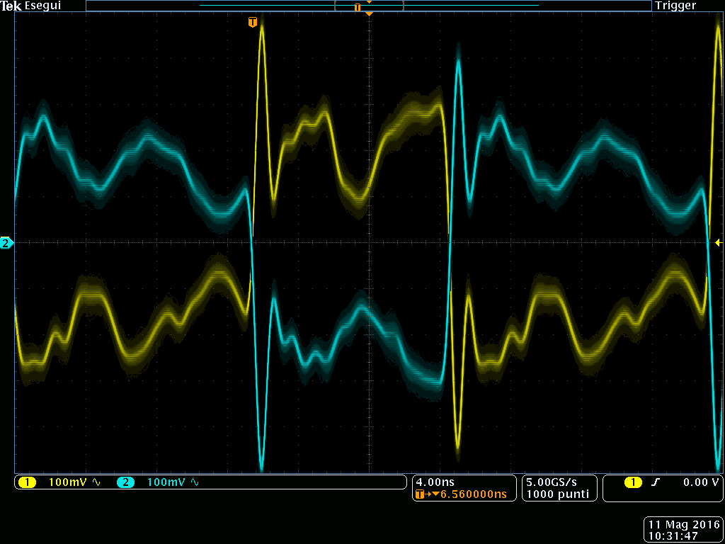
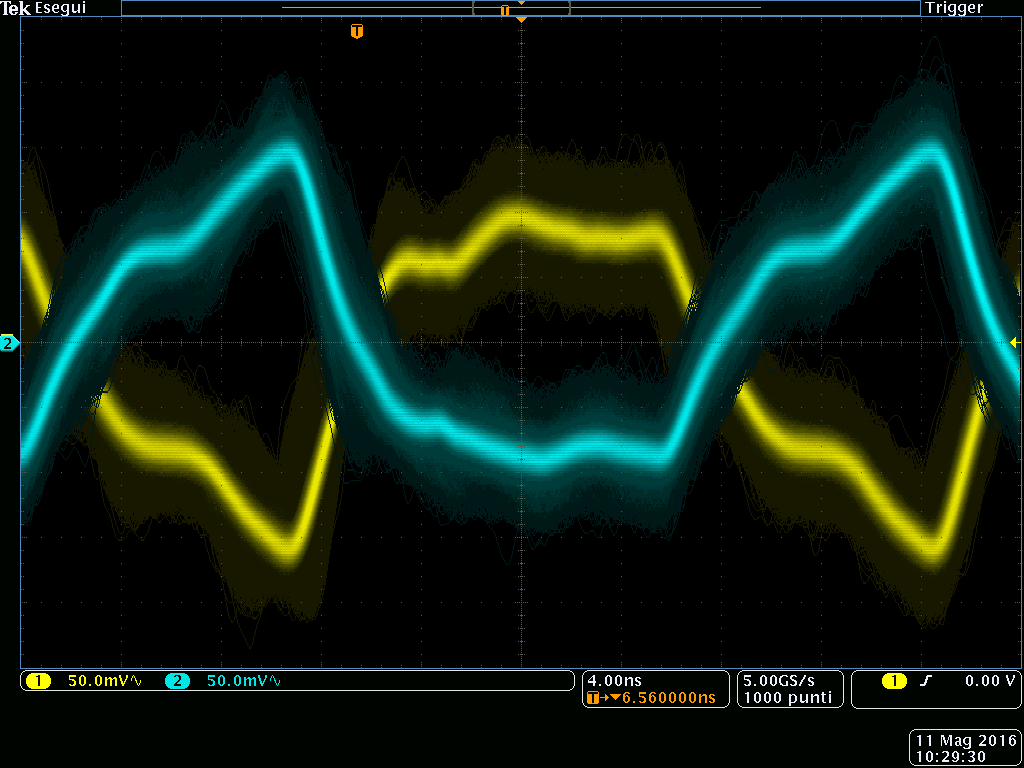
I would use the buffer DS15BR400 to transmit the LCD LVDS signals (1 Clock LVDS + 3 lane LVDS with 30MHz pixel clock) over a cable with shielded TP.
The lines are DC_coupled and well terminated with 100 Ohm on both side.

Until now I've tested the solution with different types of cable (CAT5E STP, CAT6 STP, CAT6 UTP, custom cable CAT5E S-STP) but I'm not able to exceed 10 meters also with pre-emphasis enabled.

Taking a look at the diagram showed on the datasheet I hoped to reach 30 meters of distance with a CAT5E STP cable.

Do you have any suggestion?

Thanks in advance.

  • Hi Quadrelli,

    The performance you have achieved does seem to be on the low side of expectations.  It is possible something other than the cable attenuation is limiting your performance.  I would look at the 30 MHz clock performance/jitter.  Poor input clock performance will limit the eye opening on the high speed side - reducing the cable length.  Since you have tried several cables, I do not believe it is cable pair-to-pair skew, but this is something else to be aware of.

    Can you look at the 30 MHz input clock and the LVDS output jitter?

    What serdes are you using prior to the DS15BR400?

    Thanks and Regards,

    Lee

  • Hi Lee,

    thanks for reply.

    In my application the DS15BR400 is directly connected (with 100Ohm differential stripline - max lenght 30mm) to a CPU with LVDS display interface compliant with EIA/TIA 644A (1 CLK lane at 30MHz and 3 DATA lanes at 7xFreq.CLK=210MHZ).

    The eye diagram of input signals and also the eye diagram of the output of DS15BR400 seems to be ok.

    At the end of the cable the eye diagram is corrupted.

    Best regards.

  • Hi,

    Please upload the eye diagrams if possible so we can help debug the root cause.

    It could be something in the layout at the far end which is distorting the signals.

    Regards,

    Lee

  • Hi Lee,

    I've uploaded few eye diagrams taken for two different cables:
     - 30 meters CAT5E cable
     - 20 meters Custom cable 

    The diagrams refer to CLK signal. The CLK duty cycle is not 50% and depends on CPU internal PLL.
    The eye diagram for data lines can not be taken because the streaming is not periodic.

    For each type of cable I got 3 eye diagrams:
     - at the input of DS15BR400
     - at the output of DS15BR400
     - at the end of cable (input of LCD)

    Regards.

    Manrico

    CAT5E input of DS15BR400

    CAT5E output of DS15BR400

    CAT5E end of cable

    Custom cable input of DS15BR400

    Custom cable output of DS15BR400

    Custom cable end of cable

  • Sorry for the questions.  I cannot tell if the waveform distortions are due to the probe, probe location, or layout.

    What type of probe are you using?  Differential probes are best - single ended probes tend to create  waveform distortion due to GND inductance.

    What is the bandwidth of the scope?

    What is the setting of the DS15BR400?   It could be helpful to disable any output pre-emphasis to start with.

    Thanks,

    Lee