This thread has been locked.

If you have a related question, please click the "Ask a related question" button in the top right corner. The newly created question will be automatically linked to this question.

TLK110 - PFBOUT

Other Parts Discussed in Thread: TLK110

Hi all

Would you mind if we ask TLK110?

<Question1>
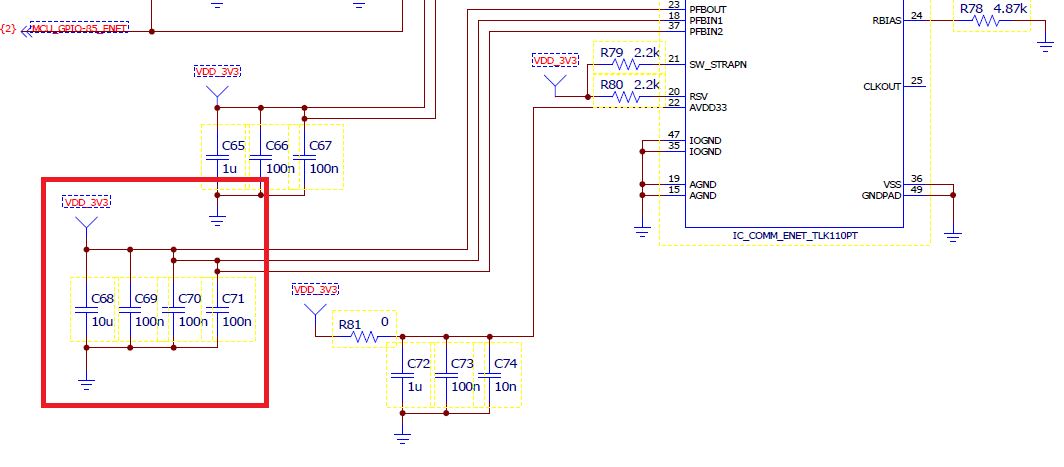
Is PFBOUT of the power source AVDO33?(divided voltage from AVDO33)

<Question2>
How much is the tolerance of PFBOUT?(1.55V±2%??) 

<Question3>
In case of  PFBOUT=PFBIN= under 1.48V, it might not operate normally?(It can't turn on the LED,,,,) 

Kind regards,

Hirotaka Matsumoto

  • Yes, PFBOUT is based on the AVDD33 supply.

    The tolerance of PFBOUT should be sufficient to meet the core supply voltage requirements for PFBIN1 and PFBIN2 shown in the datasheet, 1.48V to 1.68V.

    Operation outside the datasheet limits is not recommended. However, if PFBOUT and PFBIN are operated below the recommended limits, the most likely result would be a parametric failure, for example, a timing violation.

    Patrick
  • Hello Patrick,

    In case of F28M36x controlCARD the PFBOUT is directly connected to the 3.3V power supply. I did the same in my design but with a zero Ohm resistor and it works for me also. When I remove the resistor I can measure 1.55V on PFBOUT but in this case the PHY is not able to establish a connection.

    Do you have any idea why the connection is not established without connecting PRBOUT to the 3.3V power supply?

    Thank you in advance!

    Tamas

  • Hi Tamas,

    PFBOUT should never be connected to a 3.3V supply.
    This pin is an output of the internal regulator.

    Have you had a look at the recommended schematic for PFBOUT in the datasheet on page 9 and 10? You will see that for Dual Supply, PFBOUT must be floating and for single supply, PFBOUT must have a de-coupling cap.

    Do you mind attaching your schematic for this portion of you design? I want to make sure the connections are correct.

    Kind regards,
    Ross
  • Hi Ross,

    Thank you for the quick reply!

    I have looked the recommended schematic for PFBOUT, but in TMDSCNCD28M36 design the PFBOUT was directly connected to the power supply.

    It was a contradiction, but the controlCard worked well. I have used the recommended circuitry but I also made it possible to connect the PFBOUT to the +3.3V power supply with a 0R resistor.

    The 0R resistor was always in our circuitry and it worked very well. Now I have reviewed our design because after some months of operation for some reason the PHYs stop working. Yesterday I have removed the 0R resistor from a working device but without this the link is not established, When I tie the PFBOUT to +3.3V power supply again just like in the controlCard a link established again.

    I have attached a picture from the controlCard, but the only difference from our design is that we have the 0R resistor between 3.3V and PFBOUT.

    Do you have any idea why the PHY is not able to establish a connection with a link partern when the PFBOUT is disconnected from the +3.3V?

    Thank you for you answear in advance!

    Kind regards,
    Tamas

  • Hi Tamas,

    This is very strange indeed. Can you disconnect your PFBOUT from the 3.3V supply, then power on the device and measure the voltage on the PFBOUT pin? This voltage should be 1.48V - 1.68V as Patrick stated above.

    You may also need to reset the TLK110 after powering up the 3.3V rail using the RESET pin.

    Regards,
  • Hi  Rob,

    I have disconnected PFBOUT from the 3.3V supply. I measured 1.55V on the PFBOUT and did a reset  on the TLK110 but the connection is still not established.

    Do you think that the conntected 3.3V on PFBOUT can damage the TLK110 in the long-tem?

    Thanks and regards,
    Tamas

  • Tamas,

    As Ross stated above, the PFBOUT pin is the output of an LDO. The LDO's input is the AVDD rail. The concern I have is applying 3.3V to the PFBIN1 and PFBIN2 pins. This should not happen as they are IC core voltages that must be 1.55V +/- 5%.

    Why the device works with 3.3V applied to PFBOUT in the above schematic is bizarre. In fact I'd suspect damage with this configuration. I could not find the schematic for the control card. Can you share this entire schematic?

    Regards,
  • Tamas,

    That is an old schematic and you may have a problem with JTAG locking up the device. Can you share your own schematic?

    See this thread: e2e.ti.com/.../214049

    For an immediate test, place a pull-down on the JTAG_TRSTn line when powering up the TLK110.

    Regards,