This thread has been locked.

If you have a related question, please click the "Ask a related question" button in the top right corner. The newly created question will be automatically linked to this question.

TPS65982 how to connect the two TPS65982EVM

Other Parts Discussed in Thread: TPS65982, TPS65982-EVM

Hi

Our customer is going to evaluate TPS65982EVM.

The customer configuration is the following;

 A. The connections

  - The one TPS65982 is set the DRP mode(Conf ID#: 2)    --> supply side

  - The another TPS65982 is set the UFP mode(Conf ID#:7)  ---> receiver side 

B. The power supply

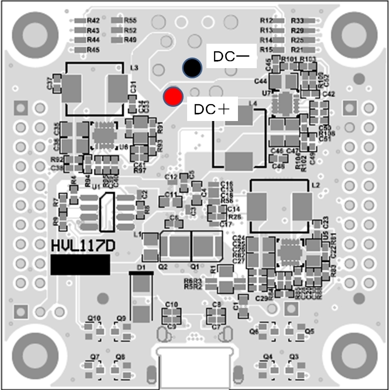
  The power supply is connected directly with the wire to the pattern of PCB because the AC Adapter which is include the EVM is not suitable in Japan.

The questions are;

  1. Is that possible to set with the above(A.) configuration?

      Our customer set the above configuration to evaluate the DRP and UFP operation with the two EVM.

      However the DCDC which is U7(TPS54335) on EVM(DRP mode) is broken. 

  2. Is the following connections possible?


Regards,

Koji Hamamoto


  • Hi Hamamoto-san,

    1. This is a good configuration to show DRP / UFP operation. If you look at Table 2 of the TPS65982-EVM User's Guide, you will find various other DRP and UFP configurations that can be used for demo evaluation.

    How did you confirm that U7 was broken? If this is the case, this EVM will not be capable of sourcing any high voltage contracts (12 or 20V) through the PP_HV path.

    2. I do not recommend using this approach to powering the EVM. In section 5.3 of the TPS65982-EVM User's Guide, you will find alternative approaches to powering the EVM. I recommend applying 20V DC (using DC supply) directly to J6 with the jumper/shunt installed. This will ensure that all power rails are properly generated.

    The TPS65982-EVM Users Guide is located at www.ti.com/.../technicaldocuments.

    Regards,
    Joey
  • Hi Joey-san

    Thank you for your support. And I apologize for the delay in replying.

    Regarding 2.,  I need more information about the configuration of the applying 20V DC directly. 

     1. Connect the + line of external DC supply to J6 with jumper/shunt installed.

     2. Where should we connect the - line of external DC supply to?

    Regarding 

    Koji Hamamoto

  • Hamamoto-san,

    You will connect the - line of DC supply to GND, which is TP5 (located above J6) or TP4 (located to the right of J6) on the TPS65982-EVM.

    Regards,

    Joey

  • Hi

    Thank you for your support.

    I have some question about your answer.

    As you mentioned , above post ( 1. This is a good configuration to show DRP / UFP operation. If you look at Table 2 of the TPS65982-EVM User's Guide, you will find various other DRP and UFP configurations that can be used for demo evaluation.)

    I think we should set DRP at ID0 if we use 20V source. (Not ID2) Is that correct?

    >>How did you confirm that U7 was broken? If this is the case, this EVM will not be capable of sourcing any high voltage contracts (12 or 20V) through the PP_HV path.

     For you question, we found some smoke on the IC (U7). That is how we knew that has been broken.

     I think HV_source(12V from U7) and external supply was conflicted at VBUS point because the source side of TPS65982EVM is ID2(not support 20V) and the sink side of TPS65982EVM is ID7(support 20V). So , we should set ID0(DRP)  at source side of TPS65982EVM. What do you think?

    Regards,

    Koji Hamamoto