


Other Parts Discussed in Thread: XIO2001
Hello,
We have a problem in a batch of our PCI Express addon cards. The cards use XIO2001 (HTQFP). The PCI Express slot doesn't initialize correctly and the card isn't recognized by BIOS. Before this batch, all the cards have worked fine (20 cards). Only 6 of the 25 cards of this batch work.
When the motherboard deasserts PERST#, the voltage measured from pin 69 (VDD_15_COMB) rises by ~0,45 volts. CH1 is PERST# and CH2 is pin 69 from XIO2001.

We managed to fix one card by changing both XIO2001 and the target PCI device. On another card, we removed the target device completely but the problem still persists. The voltage rise does not occur in the working cards or the cards from the previous batch. We did not change anything from the previous batch, even the PCBs used for this batch were from the same batch of PCBs as the last cards.
Here are the lot codes for XIO2001:
This batch: 490F4W
Previous batch: 3BC8TZW
We added 1n, 10n and 1u capacitors to the VDD_COMBIO terminals. This made no difference in the operation. The voltage still rises after PERST# is deasserted. Also, we checked again the voltages on the unused REQ# lines, everything seems correct.
We also ordered 20 new XIO2001s. We changed one to a card that is not working and now it is operating correctly. This did not happen for the next three cards however. The voltage rise still happens. The lot code for the XIO2001s that we now have tried is: 5AAT13W
The only difference we can find between a working card and a card that is not working is the voltage rise after PERST# is deasserted. There is no difference in the waveforms of PERST# or REFCLK. If we power the card from a laboratory power supply, the voltage rise does not happen. Only when it is plugged into the motherboard.
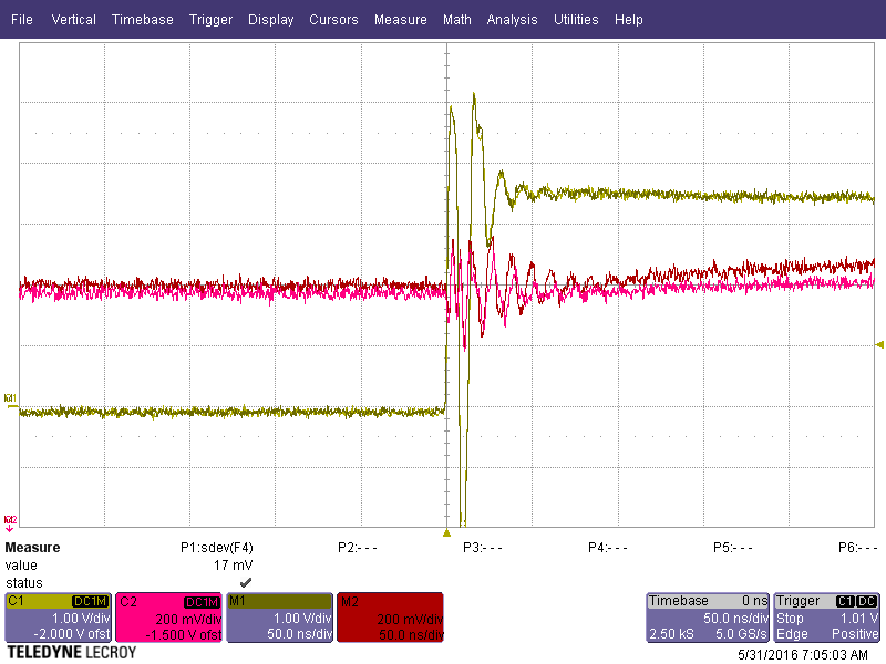
Here is a picture of PERST# and VDD_15_COMB. C1 and C2 are measured from a working card. C1 is PERST# and C2 is VDD_15_COMB. M1 and M2 are measured from a card that is not working. M1 is PERST# and M2 is VDD_15_COMB.
The PERST# waveform looks identical in both cards, but you can see the VDD_15_COMB voltage starts to rise in the card that is not working.


