This thread has been locked.

If you have a related question, please click the "Ask a related question" button in the top right corner. The newly created question will be automatically linked to this question.

SN65DSI84 bring-up

Other Parts Discussed in Thread: SN65DSI84

Hi all!

I have some questions about sn64dsi84 and I would like some help, please.

I've started working on a Jetson-TK1 platform that has two sn64dsi84 bgas to drive two lvds 1920x1080 monitors.

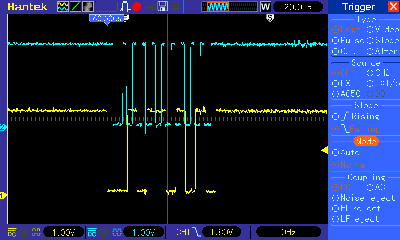
The board is ready, I've made almost everything working and now I have to bring-up the displays. I'm trying to i2c probe the chip from u-boot but it doesn't respond to any i2c commands (100KHz). I've validated the i2c commands with a scope and they are fine. The datasheet mentions that the dsi lines have to be in LP11 state to have access to the i2c registers. This means that the chip won't reply at all to any commands if the dsi output is not in LP11 state?

Only by following this init sequence the chip responds to i2c commands?

Also I'm bit confused about the i2c addresses. The datasheets refers that depending the address pin the addresses are 0x58/0x59 or 0x5a/0x5b for w/r. On the other hand there is an example script (8.2.2.1 in the datasheet) that uses the address 0x2d. The weird thing is that also the dsi2lvds driver on the tegra linux kernel uses that address, too. Also in the kernel driver there's no such init sequence that puts the dsi in low power mode to access the external dsi2lvds converter.

Do you provide a driver or I have to implement it by myself? It would be very convenient for developers if such driver existed, especially now that the tegras are so up-market and many manufacturers still using lvds displays.


Thank you in advance!

PS. I also have some other questions regarding the dsi tool and the parameters but first I have to bring up at least the displays.

Dimitris.

  • When ADDR=1,  the I2C addres is 0x5A (Write) and 0x5B (Read). That means that you will have to configure the 7-bit I2C slave address 0x2D. You can have access to the I2C registers anytime not only when the DSI lanes are in LP11 state.

    What is the PU on I2C SDA/SCL? 

    We only provide the attached code as a reference, it was developed in Linux for OMAP and configures the DSI8X. 

    Brief description:

    The file “panel-dsi85.c” executes the initial setup for the DSI8x device, specifically we use the dsi_config function to configure the DSI8x registers, this function creates a I2C_ client structure to configure the device registers from OMAP processor (this is only a sample code, the customer needs to modify the values in the code to match the required resolution, video format, etc… ).

    /*
     *
     * Copyright 2011 Texas Instruments, Inc.
     * Author: Archit Taneja <archit@ti.com>
     *
     * based on d2l panel driver by Jerry Alexander <x0135174@ti.com>
     *
     * This program iss free software; you can redistribute it and/or modify it
     * under the terms of the GNU General Public License version 2 as published by
     * the Free Software Foundation.
     *
     * This program is distributed in the hope that it will be useful, but WITHOUT
     * ANY WARRANTY; without even the implied warranty of MERCHANTABILITY or
     * FITNESS FOR A PARTICULAR PURPOSE.  See the GNU General Public License for
     * more details. 
     *
     * You should have received a copy of the GNU General Public License along with
     * this program.  If not, see <http://www.gnu.org/licenses/>.
     */
    
    #include <linux/module.h>
    #include <linux/debugfs.h>
    #include <linux/delay.h>
    #include <linux/err.h>
    #include <linux/jiffies.h>
    #include <linux/sched.h>
    #include <linux/seq_file.h>
    #include <linux/backlight.h>
    #include <linux/fb.h>
    #include <linux/interrupt.h>
    #include <linux/gpio.h>
    #include <linux/slab.h>
    #include <linux/regulator/consumer.h>
    #include <linux/mutex.h>
    #include <linux/i2c.h>
    
    #include <video/omapdss.h>
    #include <video/mipi_display.h>
    #include <video/omap-panel-dsi85.h>
    
    #include "panel-dsi85.h"
    
    #define DSI85DEBUG
    
    static struct i2c_board_info dsi85_i2c_board_info = {
    	I2C_BOARD_INFO("dsi85_i2c_driver", 0x2d /*0x2c*/),
    };
    
    struct dsi85_i2c_data {
    	struct mutex xfer_lock;
    };
    
    static struct i2c_device_id dsi85_i2c_id[] = {
    	{ "dsi85_i2c_driver", 0 },
    };
    
    #define LVDS_CLK_FROM_DSI_CLK  1
    
    struct dsi85_lvds_timings {
        u16 hfp;
        u16 hsw;
        u16 hbp;
        u16 vfp;
        u16 vsw;
        u16 vbp;
    };
    
    static struct dsi85_lvds_timings lvds_timings = {
    	.hfp = 40,
    	.hsw = 128,
    	.hbp = 40,
    	.vfp = 1,
    	.vsw = 4,
    	.vbp = 9,    
    };
    
    static struct omap_video_timings dsi85_timings = {
    	.x_res = 1024,
    	.y_res = 600,
    	.pixel_clock = 50000,
    	.hfp = 36,	//42 128 38 - 100 1 107  chido es 36 128  45
    	.hsw = 128,
    	.hbp = 45,
    	.vfp = 1,
    	.vsw = 4,
    	.vbp = 9,
    };
    
    static const struct omap_dss_dsi_videomode_data vm_data = {
    	.hsa = 1,
    	.hfp = 20,   // Set to 4/3 of the DISPC porch value.
    	.hbp = 20,   // Set to 4/3 of the DISPC porch value.
    	.vsa = 4,
    	.vfp = 6,
    	.vbp = 4,
    
        .blanking_mode = 1,    
        .hsa_blanking_mode = 1,
        .hbp_blanking_mode = 1,
        .hfp_blanking_mode = 1,
    
    	.vp_de_pol = true,
    	.vp_vsync_pol = false,
    	.vp_hsync_pol = false,
    	.vp_hsync_end = false,
    	.vp_vsync_end = false,
    
    	.window_sync = 4,
        .ddr_clk_always_on = true,
    };
    
    struct dsi85_data {
    	struct mutex lock;
    
    	struct omap_dss_device *dssdev;
    	struct backlight_device *bldev;
    	struct dentry *debug_dir;
    	bool enabled;
    	u8 rotate;
    	bool mirror;
    	bool use_dsi_bl;
    	unsigned int bl;
    	unsigned long hw_guard_end;	/* next value of jiffies when we can
    					 * issue the next sleep in/out command
    					 */
    	unsigned long hw_guard_wait;	/* max guard time in jiffies */
    
    	int config_channel;
    	int pixel_channel;
    
    	struct omap_video_timings *timings;
    
    	struct panel_dsi85_data *pdata;
    	struct i2c_client *dsi85_i2c_client;
    };
    
    struct dsi85_reg {
    	/* Address and register value */
    	u8 data[10];
    	int len;
    };
    
    static int dsi85_i2c_probe(struct i2c_client *client,
    		const struct i2c_device_id *id)
    {
    	struct dsi85_i2c_data *dsi85_i2c_data;
    
    	printk(KERN_INFO "DSI85-I2C: Probe called!\n");
    	dsi85_i2c_data = kzalloc(sizeof(struct dsi85_i2c_data), GFP_KERNEL);
    
    	if (!dsi85_i2c_data) {
    		printk(KERN_ERR "DSI85-I2C: memory allocation failed!\n");
    		return -ENOMEM;
    	}
    
    	mutex_init(&dsi85_i2c_data->xfer_lock);
    	i2c_set_clientdata(client, dsi85_i2c_data);
    
    	return 0;
    }
    
    static int dsi85_i2c_remove(struct i2c_client *client)
    {
    	struct dsi85_i2c_data *dsi85_i2c_data =
    					i2c_get_clientdata(client);
    	kfree(dsi85_i2c_data);
    	return 0;
    }
    
    static struct i2c_driver dsi85_i2c_driver = {
    	.driver = {
    		.name	= "dsi85_i2c_driver",
    	},
    	.probe		= dsi85_i2c_probe,
    	.remove		= dsi85_i2c_remove,
    	.id_table	= dsi85_i2c_id,
    };
    static void dsi85_get_timings(struct omap_dss_device *dssdev,
    			    struct omap_video_timings *timings)
    {
    	*timings = dssdev->panel.timings;
    }
    
    static void dsi85_set_timings(struct omap_dss_device *dssdev,
    			    struct omap_video_timings *timings)
    {
    	dssdev->panel.timings.x_res = timings->x_res;
    	dssdev->panel.timings.y_res = timings->y_res;
    	dssdev->panel.timings.pixel_clock = timings->pixel_clock;
    	dssdev->panel.timings.hsw = timings->hsw;
    	dssdev->panel.timings.hfp = timings->hfp;
    	dssdev->panel.timings.hbp = timings->hbp;
    	dssdev->panel.timings.vsw = timings->vsw;
    	dssdev->panel.timings.vfp = timings->vfp;
    	dssdev->panel.timings.vbp = timings->vbp;
    }
    
    static int dsi85_check_timings(struct omap_dss_device *dssdev,
    			     struct omap_video_timings *timings)
    {
    	return 0;
    }
    
    static void dsi85_get_resolution(struct omap_dss_device *dssdev,
    			       u16 *xres, u16 *yres)
    {
    	struct dsi85_data *dsi85_d = dev_get_drvdata(&dssdev->dev);
    
    	if (dsi85_d->rotate == 0 || dsi85_d->rotate == 2) {
    		*xres = dssdev->panel.timings.x_res;
    		*yres = dssdev->panel.timings.y_res;
    	} else {
    		*yres = dssdev->panel.timings.x_res;
    		*xres = dssdev->panel.timings.y_res;
    	}
    }
    
    static int dsi85_probe(struct omap_dss_device *dssdev)
    {
    	struct i2c_adapter *adapter;
    	struct i2c_client *dsi85_i2c_client;
    	int ret = 0;
    	struct dsi85_data *dsi85_d = NULL;
    
    	dev_dbg(&dssdev->dev, "dsi85_probe\n");
    
    	if (dssdev->data == NULL) {
    		dev_err(&dssdev->dev, "no platform data!\n");
    		return -EINVAL;
    	}
    
    	dssdev->panel.config = OMAP_DSS_LCD_TFT;
    	dssdev->panel.timings = dsi85_timings;
    	dssdev->panel.dsi_vm_data = vm_data;
    
    	dssdev->ctrl.pixel_size = 24;
    	dssdev->panel.acbi = 0;
    	dssdev->panel.acb = 40;
    
    	dsi85_d = kzalloc(sizeof(*dsi85_d), GFP_KERNEL);
    	if (!dsi85_d)
    		return -ENOMEM;
    
    	dsi85_d->dssdev = dssdev;
    	dsi85_d->pdata = dssdev->data;
    
    
    	if (!dsi85_d->pdata) {
    		dev_err(&dssdev->dev, "Invalid platform data\n");
    		ret = -EINVAL;
    		goto err;
    	}
    
    	mutex_init(&dsi85_d->lock);
    
    	dev_set_drvdata(&dssdev->dev, dsi85_d);
    
    	dsi85_d->debug_dir = debugfs_create_dir("dsi85", NULL);
    	if (!dsi85_d->debug_dir) {
    		dev_err(&dssdev->dev, "failed to create debug dir\n");
    		goto err_debugfs;
    	}
    
    	ret = omap_dsi_request_vc(dssdev, &dsi85_d->pixel_channel);
    	if (ret) {
    		dev_err(&dssdev->dev, "failed to request pixel update "
    		    "channel\n");
    		goto err_debugfs;
    	} else
    		printk(KERN_INFO "pixel channel setup for %d\n", \
    			dsi85_d->pixel_channel);
    
    	printk(KERN_INFO "pixel channel %d\n", dsi85_d->pixel_channel);
    	ret = omap_dsi_set_vc_id(dssdev, dsi85_d->pixel_channel, 0);
    	if (ret) {
    		dev_err(&dssdev->dev, "failed to set VC_ID for pixel data"
    			" virtual channel\n");
    		goto err_pixel_vc;
    	}
    
    	adapter = i2c_get_adapter(2);
    	if (!adapter) {
    		printk(KERN_INFO "DSI85-I2C: can't get i2c adapter 2\n");
    //		ret = -ENODEV;
    //		goto err_pixel_vc;
    	}
    
    	dsi85_i2c_client = i2c_new_device(adapter, &dsi85_i2c_board_info);
    	if (!dsi85_i2c_client) {
    		printk(KERN_INFO "DSI85-I2C: can't add i2c device\n");
    //		ret = -ENODEV;
    //		goto err_pixel_vc;
    	}
    
    	dsi85_d->dsi85_i2c_client = dsi85_i2c_client;
    
    	ret = i2c_smbus_read_byte_data(dsi85_i2c_client, 0x00);
    	printk(KERN_INFO "DSI85-I2C: reading 0x00 returned - 0x%x\n", ret);
    
    	dev_dbg(&dssdev->dev, "dsi85_probe\n");
    	return 0;
    
    err_pixel_vc:
    	omap_dsi_release_vc(dssdev, dsi85_d->pixel_channel);
    err_debugfs:
    	mutex_destroy(&dsi85_d->lock);
    	gpio_free(dsi85_d->pdata->reset_gpio);
    err:
    	kfree(dsi85_d);
    
    	return ret;
    }
    
    static void dsi85_remove(struct omap_dss_device *dssdev)
    {
    	struct dsi85_data *dsi85_d = dev_get_drvdata(&dssdev->dev);
    	debugfs_remove_recursive(dsi85_d->debug_dir);
    	mutex_destroy(&dsi85_d->lock);
    	gpio_free(dsi85_d->pdata->reset_gpio);
    	kfree(dsi85_d);
    }
    
    #ifdef DSI85DEBUG
    static void dsi85_dumpconfig(struct omap_dss_device *dssdev)
    {
    	struct dsi85_data *dsi85_d = dev_get_drvdata(&dssdev->dev);
    	struct i2c_client *dsi85_i2c_client = dsi85_d->dsi85_i2c_client;
    	printk(KERN_INFO "luis' message");
    	printk(KERN_INFO "DSI85-I2C: read 0x%02x  - 0x%02x\n", 0x00, \
    	i2c_smbus_read_byte_data(dsi85_i2c_client, 0x00));
    	/*
    	printk(KERN_INFO "DSI85-I2C: read 0x%02x  - 0x%02x\n", 0x01, \
    	i2c_smbus_read_byte_data(dsi85_i2c_client, 0x01));
    
    	printk(KERN_INFO "DSI85-I2C: read 0x%02x  - 0x%02x\n", 0x02, \
    	i2c_smbus_read_byte_data(dsi85_i2c_client, 0x02));
    	
    	printk(KERN_INFO "DSI85-I2C: read 0x%02x  - 0x%02x\n", 0x03, \
    	i2c_smbus_read_byte_data(dsi85_i2c_client, 0x03));
    	printk(KERN_INFO "DSI85-I2C: read 0x%02x  - 0x%02x\n", 0x04, \
    	i2c_smbus_read_byte_data(dsi85_i2c_client, 0x04));
    	
    	printk(KERN_INFO "DSI85-I2C: read 0x%02x  - 0x%02x\n", 0x05, \
    	i2c_smbus_read_byte_data(dsi85_i2c_client, 0x05));
    	*/
    	
    
    	printk(KERN_INFO "DSI85-I2C: read 0x%02x  - 0x%02x\n", 0x0D, \
    		i2c_smbus_read_byte_data(dsi85_i2c_client, 0x0D));
    	printk(KERN_INFO "DSI85-I2C: read 0x%02x  - 0x%02x\n", 0x0A, \
    		i2c_smbus_read_byte_data(dsi85_i2c_client, 0x0A));
    	printk(KERN_INFO "DSI85-I2C: read 0x%02x  - 0x%02x\n", 0x0B, \
    		i2c_smbus_read_byte_data(dsi85_i2c_client, 0x0B));
    	printk(KERN_INFO "DSI85-I2C: read 0x%02x  - 0x%02x\n", 0x10, \
    		i2c_smbus_read_byte_data(dsi85_i2c_client, 0x10));
    	printk(KERN_INFO "DSI85-I2C: read 0x%02x  - 0x%02x\n", 0x18, \
    		i2c_smbus_read_byte_data(dsi85_i2c_client, 0x18));
    	printk(KERN_INFO "DSI85-I2C: read 0x%02x  - 0x%02x\n", 0x1A, \
    		i2c_smbus_read_byte_data(dsi85_i2c_client, 0x1A));
    	printk(KERN_INFO "DSI85-I2C: read 0x%02x  - 0x%02x\n", 0x20, \
    		i2c_smbus_read_byte_data(dsi85_i2c_client, 0x20));
    	printk(KERN_INFO "DSI85-I2C: read 0x%02x  - 0x%02x\n", 0x21, \
    		i2c_smbus_read_byte_data(dsi85_i2c_client, 0x21));
    	printk(KERN_INFO "DSI85-I2C: read 0x%02x  - 0x%02x\n", 0x22, \
    		i2c_smbus_read_byte_data(dsi85_i2c_client, 0x22));
    	printk(KERN_INFO "DSI85-I2C: read 0x%02x  - 0x%02x\n", 0x23, \
    		i2c_smbus_read_byte_data(dsi85_i2c_client, 0x23));
    	printk(KERN_INFO "DSI85-I2C: read 0x%02x  - 0x%02x\n", 0x24, \
    		i2c_smbus_read_byte_data(dsi85_i2c_client, 0x24));
    	printk(KERN_INFO "DSI85-I2C: read 0x%02x  - 0x%02x\n", 0x25, \
    		i2c_smbus_read_byte_data(dsi85_i2c_client, 0x25));
    	printk(KERN_INFO "DSI85-I2C: read 0x%02x  - 0x%02x\n", 0x26, \
    		i2c_smbus_read_byte_data(dsi85_i2c_client, 0x26));
    	printk(KERN_INFO "DSI85-I2C: read 0x%02x  - 0x%02x\n", 0x27, \
    		i2c_smbus_read_byte_data(dsi85_i2c_client, 0x27));
    	printk(KERN_INFO "DSI85-I2C: read 0x%02x  - 0x%02x\n", 0x28, \
    		i2c_smbus_read_byte_data(dsi85_i2c_client, 0x28));
    	printk(KERN_INFO "DSI85-I2C: read 0x%02x  - 0x%02x\n", 0x29, \
    		i2c_smbus_read_byte_data(dsi85_i2c_client, 0x29));
    	printk(KERN_INFO "DSI85-I2C: read 0x%02x  - 0x%02x\n", 0x2A, \
    		i2c_smbus_read_byte_data(dsi85_i2c_client, 0x2A));
    	printk(KERN_INFO "DSI85-I2C: read 0x%02x  - 0x%02x\n", 0x2B, \
    		i2c_smbus_read_byte_data(dsi85_i2c_client, 0x2B));
    	printk(KERN_INFO "DSI85-I2C: read 0x%02x  - 0x%02x\n", 0x2C, \
    		i2c_smbus_read_byte_data(dsi85_i2c_client, 0x2C));
    	printk(KERN_INFO "DSI85-I2C: read 0x%02x  - 0x%02x\n", 0x2D, \
    		i2c_smbus_read_byte_data(dsi85_i2c_client, 0x2D));
    	printk(KERN_INFO "DSI85-I2C: read 0x%02x  - 0x%02x\n", 0x2E, \
    		i2c_smbus_read_byte_data(dsi85_i2c_client, 0x2E));
    	printk(KERN_INFO "DSI85-I2C: read 0x%02x  - 0x%02x\n", 0x2F, \
    		i2c_smbus_read_byte_data(dsi85_i2c_client, 0x2F));
    	printk(KERN_INFO "DSI85-I2C: read 0x%02x  - 0x%02x\n", 0x30, \
    		i2c_smbus_read_byte_data(dsi85_i2c_client, 0x30));
    	printk(KERN_INFO "DSI85-I2C: read 0x%02x  - 0x%02x\n", 0x31, \
    		i2c_smbus_read_byte_data(dsi85_i2c_client, 0x31));
    	printk(KERN_INFO "DSI85-I2C: read 0x%02x  - 0x%02x\n", 0x32, \
    		i2c_smbus_read_byte_data(dsi85_i2c_client, 0x32));
    	printk(KERN_INFO "DSI85-I2C: read 0x%02x  - 0x%02x\n", 0x33, \
    		i2c_smbus_read_byte_data(dsi85_i2c_client, 0x33));
    	printk(KERN_INFO "DSI85-I2C: read 0x%02x  - 0x%02x\n", 0x34, \
    		i2c_smbus_read_byte_data(dsi85_i2c_client, 0x34));
    	printk(KERN_INFO "DSI85-I2C: read 0x%02x  - 0x%02x\n", 0x35, \
    		i2c_smbus_read_byte_data(dsi85_i2c_client, 0x35));
    	printk(KERN_INFO "DSI85-I2C: read 0x%02x  - 0x%02x\n", 0x36, \
    		i2c_smbus_read_byte_data(dsi85_i2c_client, 0x32));
    	printk(KERN_INFO "DSI85-I2C: read 0x%02x  - 0x%02x\n", 0x37, \
    		i2c_smbus_read_byte_data(dsi85_i2c_client, 0x33));
    	printk(KERN_INFO "DSI85-I2C: read 0x%02x  - 0x%02x\n", 0x38, \
    		i2c_smbus_read_byte_data(dsi85_i2c_client, 0x34));
    	printk(KERN_INFO "DSI85-I2C: read 0x%02x  - 0x%02x\n", 0x39, \
    		i2c_smbus_read_byte_data(dsi85_i2c_client, 0x35));
    	printk(KERN_INFO "DSI85-I2C: read 0x%02x  - 0x%02x\n", 0x3A, \
    		i2c_smbus_read_byte_data(dsi85_i2c_client, 0x35));
    	printk(KERN_INFO "DSI85-I2C: read 0x%02x  - 0x%02x\n", 0x3B, \
    		i2c_smbus_read_byte_data(dsi85_i2c_client, 0x3B));
    }
    
    #endif


    /**
     * dsi85_config - Configure dsi85
     *
     * Initial configuration for dsi85 configuration registers
     */
    static void dsi85_config(struct omap_dss_device *dssdev)
    {
    	printk(KERN_INFO "Now Configuring\n");
    	
    	struct dsi85_data *dsi85_d = dev_get_drvdata(&dssdev->dev);
    	struct i2c_client *dsi85_i2c_client = dsi85_d->dsi85_i2c_client;
        u8 val = 0;
    
    	/* Soft reset and disable PLL */
    	i2c_smbus_write_byte_data(dsi85_i2c_client, DSI85_SOFT_RESET, 0x01);
    	i2c_smbus_write_byte_data(dsi85_i2c_client, DSI85_PLL_EN, 0x00);
    
    #if LVDS_CLK_FROM_DSI_CLK
        val = 0x1;
    #endif
    
    	/* user external clock reference with no muliplier */
        if (dssdev->panel.timings.pixel_clock <= 37500)
        {
            // Do nothing.
        }
        else if (dssdev->panel.timings.pixel_clock <= 62500)
        {
            val |= (0x01 << 1);
        }
        else if (dssdev->panel.timings.pixel_clock <= 87500)
        {
            val |= (0x02 << 1);
        }
        else if (dssdev->panel.timings.pixel_clock <= 112500)
        {
            val |= (0x03 << 1);
        }
        else if (dssdev->panel.timings.pixel_clock <= 137500)
        {
            val |= (0x04 << 1);
        }
        else
        {
            val |= (0x05 << 1);
        }
    	i2c_smbus_write_byte_data(dsi85_i2c_client, DSI85_CORE_PLL, val);
    #if LVDS_CLK_FROM_DSI_CLK
    	i2c_smbus_write_byte_data(dsi85_i2c_client, DSI85_PLL_DIV, 0x10);  // Divide DSI_CLK by 3.
    #else
    	i2c_smbus_write_byte_data(dsi85_i2c_client, DSI85_PLL_DIV, 0x00);  // Multiply REFCLK by 1.
    #endif
    
    	/* four DSI lanes with single channel*/
    	i2c_smbus_write_byte_data(dsi85_i2c_client, DSI85_DSI_CFG, 0x20);
    	i2c_smbus_write_byte_data(dsi85_i2c_client, DSI85_DSI_EQ, 0x00);
    
        /* set DSI clock range */
        i2c_smbus_write_byte_data(dsi85_i2c_client, DSI85_CHA_DSI_CLK_RNG, (dssdev->panel.timings.pixel_clock * 3 / 5000));
        i2c_smbus_write_byte_data(dsi85_i2c_client, DSI85_CHB_DSI_CLK_RNG, (dssdev->panel.timings.pixel_clock * 3 / 5000));
    
    	/* set LVDS for single channel, 24 bit mode, HS/VS low, DE high */
    	i2c_smbus_write_byte_data(dsi85_i2c_client, DSI85_LVDS_MODE, 0x7F);
    
    	/* set LVDS 200 Ohm termination and max differential swing voltage */
    	i2c_smbus_write_byte_data(dsi85_i2c_client, DSI85_LVDS_SIGN, 0x00);
    	i2c_smbus_write_byte_data(dsi85_i2c_client, DSI85_LVDS_TERM, 0x00);
    
    	/* x resolution high/low for channel A */
    	i2c_smbus_write_byte_data(dsi85_i2c_client, DSI85_CHA_LINE_LEN_LO, \
    		((dssdev->panel.timings.x_res) & 0x00FF));
    	i2c_smbus_write_byte_data(dsi85_i2c_client, DSI85_CHA_LINE_LEN_HI, \
    		((dssdev->panel.timings.x_res) & 0xFF00)>>8);
    
    	/* x resolution high/low for channel B */
    	i2c_smbus_write_byte_data(dsi85_i2c_client, DSI85_CHB_LINE_LEN_LO, \
    		(dssdev->panel.timings.x_res & 0x00FF));
    	i2c_smbus_write_byte_data(dsi85_i2c_client, DSI85_CHB_LINE_LEN_HI, \
    		(dssdev->panel.timings.x_res & 0xFF00)>>8);
    
    	/* y resolution high/low for channel A */
    	i2c_smbus_write_byte_data(dsi85_i2c_client, DSI85_CHA_VERT_LINES_LO, \
    		(dssdev->panel.timings.y_res & 0x00FF));
    	i2c_smbus_write_byte_data(dsi85_i2c_client, DSI85_CHA_VERT_LINES_HI, \
    		(dssdev->panel.timings.y_res & 0xFF00)>>8);
    
    	/* y resolution high/low for channel B */
    	i2c_smbus_write_byte_data(dsi85_i2c_client, DSI85_CHB_VERT_LINES_LO, \
    		(dssdev->panel.timings.y_res & 0x00FF));
    	i2c_smbus_write_byte_data(dsi85_i2c_client, DSI85_CHB_VERT_LINES_HI, \
    		(dssdev->panel.timings.y_res & 0xFF00)>>8);
    
    	/* SYNC delay high/low for channel A */
    	i2c_smbus_write_byte_data(dsi85_i2c_client, \
    		DSI85_CHA_SYNC_DELAY_LO, 0x00);
    	i2c_smbus_write_byte_data(dsi85_i2c_client, \
    		DSI85_CHA_SYNC_DELAY_HI, 0x02);
    
    	/* SYNC delay high/low for channel B */
    	i2c_smbus_write_byte_data(dsi85_i2c_client, \
    		DSI85_CHB_SYNC_DELAY_LO, 0x00);
    	i2c_smbus_write_byte_data(dsi85_i2c_client, \
    		DSI85_CHB_SYNC_DELAY_HI, 0x02);
    
    	/* HSYNC width high/low for channel A */
    /*	i2c_smbus_write_byte_data(dsi85_i2c_client, DSI85_CHA_HSYNC_WIDTH_LO, \
    		(dssdev->panel.timings.hsw & 0x00FF));
    	i2c_smbus_write_byte_data(dsi85_i2c_client, DSI85_CHA_HSYNC_WIDTH_HI, \
    		(dssdev->panel.timings.hsw & 0xFF00)>>8);	*/
        i2c_smbus_write_byte_data(dsi85_i2c_client, DSI85_CHA_HSYNC_WIDTH_LO, \
    		(lvds_timings.hsw & 0x00FF));
    	i2c_smbus_write_byte_data(dsi85_i2c_client, DSI85_CHA_HSYNC_WIDTH_HI, \
    		(lvds_timings.hsw & 0xFF00)>>8);
    
    	/* HSYNC width high/low for channel B */
    /*	i2c_smbus_write_byte_data(dsi85_i2c_client, DSI85_CHB_HSYNC_WIDTH_LO, \
    		(dssdev->panel.timings.hsw & 0x00FF));
    	i2c_smbus_write_byte_data(dsi85_i2c_client, DSI85_CHB_HSYNC_WIDTH_HI, \
    		(dssdev->panel.timings.hsw & 0xFF00)>>8); */
    	i2c_smbus_write_byte_data(dsi85_i2c_client, DSI85_CHB_HSYNC_WIDTH_LO, \
    		(lvds_timings.hsw & 0x00FF));
    	i2c_smbus_write_byte_data(dsi85_i2c_client, DSI85_CHB_HSYNC_WIDTH_HI, \
    		(lvds_timings.hsw & 0xFF00)>>8);
    
    	/* VSYNC width high/low for channel A */
    	i2c_smbus_write_byte_data(dsi85_i2c_client, DSI85_CHA_VSYNC_WIDTH_LO, \
    		(lvds_timings.vsw & 0x00FF));
    	i2c_smbus_write_byte_data(dsi85_i2c_client, DSI85_CHA_VSYNC_WIDTH_HI, \
    		(lvds_timings.vsw & 0xFF00)>>8);
    
    	/* VSYNC width high/low for channel B */
    	i2c_smbus_write_byte_data(dsi85_i2c_client, DSI85_CHB_VSYNC_WIDTH_LO, \
    		(lvds_timings.vsw & 0x00FF));
    	i2c_smbus_write_byte_data(dsi85_i2c_client, DSI85_CHB_VSYNC_WIDTH_HI, \
    		(lvds_timings.vsw & 0xFF00)>>8);
    
    	/* Horizontal BackPorch for channel A */
    //	i2c_smbus_write_byte_data(dsi85_i2c_client, DSI85_CHA_HORZ_BACKPORCH, \
    //		(dssdev->panel.timings.hbp & 0x00FF));
    	i2c_smbus_write_byte_data(dsi85_i2c_client, DSI85_CHA_HORZ_BACKPORCH, \
    		(lvds_timings.hbp & 0x00FF));
    
    	/* Horizontal BackPorch for channel B */
    //	i2c_smbus_write_byte_data(dsi85_i2c_client, DSI85_CHB_HORZ_BACKPORCH, \
    //  	(dssdev->panel.timings.hbp & 0x00FF));
    	i2c_smbus_write_byte_data(dsi85_i2c_client, DSI85_CHB_HORZ_BACKPORCH, \
    		(lvds_timings.hbp & 0x00FF));
    
    	/* Vertical BackPorch for channel A */
    	i2c_smbus_write_byte_data(dsi85_i2c_client, DSI85_CHA_VERT_BACKPORCH, \
    		(lvds_timings.vbp & 0x00FF)); 
    
    	/* Vertical BackPorch for channel B */
    	i2c_smbus_write_byte_data(dsi85_i2c_client, DSI85_CHB_VERT_BACKPORCH, \
    		(lvds_timings.vbp & 0x00FF));
    
    	/* Horizontal FrontPorch for channel A */
    //	i2c_smbus_write_byte_data(dsi85_i2c_client, DSI85_CHA_HORZ_FRONTPORCH, \
    //		(dssdev->panel.timings.hfp & 0x00FF));
    	i2c_smbus_write_byte_data(dsi85_i2c_client, DSI85_CHA_HORZ_FRONTPORCH, \
    		(lvds_timings.hfp & 0x00FF));
    
    	/* Horizontal FrontPorch for channel B */
    //	i2c_smbus_write_byte_data(dsi85_i2c_client, DSI85_CHB_HORZ_FRONTPORCH, \
    //		(dssdev->panel.timings.hfp & 0x00FF));
    	i2c_smbus_write_byte_data(dsi85_i2c_client, DSI85_CHB_HORZ_FRONTPORCH, \
    		(lvds_timings.hfp & 0x00FF));
    
    	/* Vertical FrontPorch for channel A */
    	i2c_smbus_write_byte_data(dsi85_i2c_client, DSI85_CHA_VERT_FRONTPORCH, \
    		(lvds_timings.vbp & 0x00FF));
    
    	/* Vertical FrontPorch for channel B */
    	i2c_smbus_write_byte_data(dsi85_i2c_client, DSI85_CHB_VERT_FRONTPORCH, \
    		(lvds_timings.vbp & 0x00FF));
    
    	/* Soft reset and enable PLL */
    	i2c_smbus_write_byte_data(dsi85_i2c_client, DSI85_SOFT_RESET, 0x01);
    	i2c_smbus_write_byte_data(dsi85_i2c_client, DSI85_PLL_EN, 0x01);
    	return;
    }
    
    static void dsi85_test(struct omap_dss_device *dssdev)
    {
    	printk(KERN_INFO "Now Configuring Test Pattern\n");
    	
    	struct dsi85_data *dsi85_d = dev_get_drvdata(&dssdev->dev);
    	struct i2c_client *dsi85_i2c_client = dsi85_d->dsi85_i2c_client;
        u8 val = 0;
    
    	/* Soft reset and disable PLL */
    	i2c_smbus_write_byte_data(dsi85_i2c_client, DSI85_SOFT_RESET, 0x01);
    	i2c_smbus_write_byte_data(dsi85_i2c_client, DSI85_PLL_EN, 0x00);
    
    #if LVDS_CLK_FROM_DSI_CLK
        val = 0x1;
    #endif
    
    	/* user external clock reference with no muliplier */
        if (dssdev->panel.timings.pixel_clock <= 37500)
        {
            // Do nothing.
        }
        else if (dssdev->panel.timings.pixel_clock <= 62500)
        {
            val |= (0x01 << 1);
        }
        else if (dssdev->panel.timings.pixel_clock <= 87500)
        {
            val |= (0x02 << 1);
        }
        else if (dssdev->panel.timings.pixel_clock <= 112500)
        {
            val |= (0x03 << 1);
        }
        else if (dssdev->panel.timings.pixel_clock <= 137500)
        {
            val |= (0x04 << 1);
        }
        else
        {
            val |= (0x05 << 1);
        }
        
        //LADLDL
        printk(KERN_INFO "Pixel CLK value was %d\n",val);
        
    	i2c_smbus_write_byte_data(dsi85_i2c_client, DSI85_CORE_PLL, val);
    #if LVDS_CLK_FROM_DSI_CLK
    	i2c_smbus_write_byte_data(dsi85_i2c_client, DSI85_PLL_DIV, 0x10);  // Divide DSI_CLK by 3.
    #else
    	i2c_smbus_write_byte_data(dsi85_i2c_client, DSI85_PLL_DIV, 0x00);  // Multiply REFCLK by 1.
    #endif
    
    
    	//LADLDL PLL enable after address A and B configured
    	i2c_smbus_write_byte_data(dsi85_i2c_client, DSI85_PLL_EN, 0x01);


    	/* four DSI lanes with single channel*/
    	i2c_smbus_write_byte_data(dsi85_i2c_client, DSI85_DSI_CFG, 0x20);
    	i2c_smbus_write_byte_data(dsi85_i2c_client, DSI85_DSI_EQ, 0x00);
    
        /* set DSI clock range */
        i2c_smbus_write_byte_data(dsi85_i2c_client, DSI85_CHA_DSI_CLK_RNG, (dssdev->panel.timings.pixel_clock * 3 / 5000));
        i2c_smbus_write_byte_data(dsi85_i2c_client, DSI85_CHB_DSI_CLK_RNG, (dssdev->panel.timings.pixel_clock * 3 / 5000));
    
    	/* set LVDS for single channel, 24 bit mode, HS/VS low, DE high */
    	//i2c_smbus_write_byte_data(dsi85_i2c_client, DSI85_LVDS_MODE, 0x7F);
    	/*LADLD set LVDS for single channel, 24 bit mode, HS/VS low, DE high */
    	i2c_smbus_write_byte_data(dsi85_i2c_client, DSI85_LVDS_MODE, 0x60);
    
    	/* set LVDS 200 Ohm termination and max differential swing voltage */
    	//LADLDL
    	//i2c_smbus_write_byte_data(dsi85_i2c_client, DSI85_LVDS_SIGN, 0x00);
    	//i2c_smbus_write_byte_data(dsi85_i2c_client, DSI85_LVDS_TERM, 0x00);
    
    	/* x resolution high/low for channel A */
    	i2c_smbus_write_byte_data(dsi85_i2c_client, DSI85_CHA_LINE_LEN_LO, \
    		((dssdev->panel.timings.x_res) & 0x00FF));
    	i2c_smbus_write_byte_data(dsi85_i2c_client, DSI85_CHA_LINE_LEN_HI, \
    		((dssdev->panel.timings.x_res) & 0xFF00)>>8);
    
    	/* x resolution high/low for channel B */
    	i2c_smbus_write_byte_data(dsi85_i2c_client, DSI85_CHB_LINE_LEN_LO, \
    		(dssdev->panel.timings.x_res & 0x00FF));
    	i2c_smbus_write_byte_data(dsi85_i2c_client, DSI85_CHB_LINE_LEN_HI, \
    		(dssdev->panel.timings.x_res & 0xFF00)>>8);
    
    	/* y resolution high/low for channel A */
    	i2c_smbus_write_byte_data(dsi85_i2c_client, DSI85_CHA_VERT_LINES_LO, \
    		(dssdev->panel.timings.y_res & 0x00FF));
    	i2c_smbus_write_byte_data(dsi85_i2c_client, DSI85_CHA_VERT_LINES_HI, \
    		(dssdev->panel.timings.y_res & 0xFF00)>>8);
    
    	/* y resolution high/low for channel B */
    	i2c_smbus_write_byte_data(dsi85_i2c_client, DSI85_CHB_VERT_LINES_LO, \
    		(dssdev->panel.timings.y_res & 0x00FF));
    	i2c_smbus_write_byte_data(dsi85_i2c_client, DSI85_CHB_VERT_LINES_HI, \
    		(dssdev->panel.timings.y_res & 0xFF00)>>8);
    
    	/* SYNC delay high/low for channel A */
    	i2c_smbus_write_byte_data(dsi85_i2c_client, \
    		DSI85_CHA_SYNC_DELAY_LO, 0x00);
    	i2c_smbus_write_byte_data(dsi85_i2c_client, \
    		DSI85_CHA_SYNC_DELAY_HI, 0x02);
    
    	/* SYNC delay high/low for channel B */
    	i2c_smbus_write_byte_data(dsi85_i2c_client, \
    		DSI85_CHB_SYNC_DELAY_LO, 0x00);
    	i2c_smbus_write_byte_data(dsi85_i2c_client, \
    		DSI85_CHB_SYNC_DELAY_HI, 0x02);
    
    	/* HSYNC width high/low for channel A */
    /*	i2c_smbus_write_byte_data(dsi85_i2c_client, DSI85_CHA_HSYNC_WIDTH_LO, \
    		(dssdev->panel.timings.hsw & 0x00FF));
    	i2c_smbus_write_byte_data(dsi85_i2c_client, DSI85_CHA_HSYNC_WIDTH_HI, \
    		(dssdev->panel.timings.hsw & 0xFF00)>>8);	*/
        i2c_smbus_write_byte_data(dsi85_i2c_client, DSI85_CHA_HSYNC_WIDTH_LO, \
    		(lvds_timings.hsw & 0x00FF));
    	i2c_smbus_write_byte_data(dsi85_i2c_client, DSI85_CHA_HSYNC_WIDTH_HI, \
    		(lvds_timings.hsw & 0xFF00)>>8);
    
    	/* HSYNC width high/low for channel B */
    /*	i2c_smbus_write_byte_data(dsi85_i2c_client, DSI85_CHB_HSYNC_WIDTH_LO, \
    		(dssdev->panel.timings.hsw & 0x00FF));
    	i2c_smbus_write_byte_data(dsi85_i2c_client, DSI85_CHB_HSYNC_WIDTH_HI, \
    		(dssdev->panel.timings.hsw & 0xFF00)>>8); */
    	i2c_smbus_write_byte_data(dsi85_i2c_client, DSI85_CHB_HSYNC_WIDTH_LO, \
    		(lvds_timings.hsw & 0x00FF));
    	i2c_smbus_write_byte_data(dsi85_i2c_client, DSI85_CHB_HSYNC_WIDTH_HI, \
    		(lvds_timings.hsw & 0xFF00)>>8);
    
    	/* VSYNC width high/low for channel A */
    	i2c_smbus_write_byte_data(dsi85_i2c_client, DSI85_CHA_VSYNC_WIDTH_LO, \
    		(lvds_timings.vsw & 0x00FF));
    	i2c_smbus_write_byte_data(dsi85_i2c_client, DSI85_CHA_VSYNC_WIDTH_HI, \
    		(lvds_timings.vsw & 0xFF00)>>8);
    
    	/* VSYNC width high/low for channel B */
    	i2c_smbus_write_byte_data(dsi85_i2c_client, DSI85_CHB_VSYNC_WIDTH_LO, \
    		(lvds_timings.vsw & 0x00FF));
    	i2c_smbus_write_byte_data(dsi85_i2c_client, DSI85_CHB_VSYNC_WIDTH_HI, \
    		(lvds_timings.vsw & 0xFF00)>>8);
    
    	/* Horizontal BackPorch for channel A */
    //	i2c_smbus_write_byte_data(dsi85_i2c_client, DSI85_CHA_HORZ_BACKPORCH, \
    //		(dssdev->panel.timings.hbp & 0x00FF));
    	i2c_smbus_write_byte_data(dsi85_i2c_client, DSI85_CHA_HORZ_BACKPORCH, \
    		(lvds_timings.hbp & 0x00FF));
    
    	/* Horizontal BackPorch for channel B */
    //	i2c_smbus_write_byte_data(dsi85_i2c_client, DSI85_CHB_HORZ_BACKPORCH, \
    //  	(dssdev->panel.timings.hbp & 0x00FF));
    	i2c_smbus_write_byte_data(dsi85_i2c_client, DSI85_CHB_HORZ_BACKPORCH, \
    		(lvds_timings.hbp & 0x00FF));
    
    	/* Vertical BackPorch for channel A */
    	i2c_smbus_write_byte_data(dsi85_i2c_client, DSI85_CHA_VERT_BACKPORCH, \
    		(lvds_timings.vbp & 0x00FF)); 
    
    	/* Vertical BackPorch for channel B */
    	i2c_smbus_write_byte_data(dsi85_i2c_client, DSI85_CHB_VERT_BACKPORCH, \
    		(lvds_timings.vbp & 0x00FF));
    
    	/* Horizontal FrontPorch for channel A */
    //	i2c_smbus_write_byte_data(dsi85_i2c_client, DSI85_CHA_HORZ_FRONTPORCH, \
    //		(dssdev->panel.timings.hfp & 0x00FF));
    	i2c_smbus_write_byte_data(dsi85_i2c_client, DSI85_CHA_HORZ_FRONTPORCH, \
    		(lvds_timings.hfp & 0x00FF));
    
    	/* Horizontal FrontPorch for channel B */
    //	i2c_smbus_write_byte_data(dsi85_i2c_client, DSI85_CHB_HORZ_FRONTPORCH, \
    //		(dssdev->panel.timings.hfp & 0x00FF));
    	i2c_smbus_write_byte_data(dsi85_i2c_client, DSI85_CHB_HORZ_FRONTPORCH, \
    		(lvds_timings.hfp & 0x00FF));
    
    	/* Vertical FrontPorch for channel A */
    	i2c_smbus_write_byte_data(dsi85_i2c_client, DSI85_CHA_VERT_FRONTPORCH, \
    		(lvds_timings.vbp & 0x00FF));
    
    	/* Vertical FrontPorch for channel B */
    	i2c_smbus_write_byte_data(dsi85_i2c_client, DSI85_CHB_VERT_FRONTPORCH, \
    		(lvds_timings.vbp & 0x00FF));
    
    	//Test Pattern
    	i2c_smbus_write_byte_data(dsi85_i2c_client, 0x3C, 0x11);
    
    	//LADLDL
    	/* Soft reset and enable PLL */
    	//i2c_smbus_write_byte_data(dsi85_i2c_client, DSI85_SOFT_RESET, 0x01);
    	//i2c_smbus_write_byte_data(dsi85_i2c_client, DSI85_PLL_EN, 0x01);
    	return;
    }
    
    static int dsi85_power_on(struct omap_dss_device *dssdev)
    {
    	struct dsi85_data *dsi85_d = dev_get_drvdata(&dssdev->dev);
    	int ret = 0;
    
    	if (dsi85_d->enabled != 1) {
    		if (dsi85_d->pdata->set_power)
    			dsi85_d->pdata->set_power(true);
    
    		ret = omapdss_dsi_display_enable(dssdev);
    		if (ret) {
    			dev_err(&dssdev->dev, "failed to enable DSI\n");
    			goto err;
    		}
    
    		omapdss_dsi_vc_enable_hs(dssdev, dsi85_d->pixel_channel, true);
    
    		dsi_videomode_panel_preinit(dssdev, dsi85_d->pixel_channel);
    
    		msleep(100);
    
    		//LADLDL
    		dsi85_config(dssdev);
    		//dsi85_test(dssdev);
    #ifdef DSI85DEBUG
    		dsi85_dumpconfig(dssdev);
    #endif
    		dsi_video_mode_enable(dssdev, dsi85_d->pixel_channel);
    
    		dsi85_d->enabled = 1;
    	}
    
    err:
    	return ret;
    }
    
    static void dsi85_power_off(struct omap_dss_device *dssdev)
    {
    	struct dsi85_data *dsi85_d = dev_get_drvdata(&dssdev->dev);
    
    	gpio_set_value(dsi85_d->pdata->reset_gpio, 0);
    	msleep(20);
    
    	dsi85_d->enabled = 0;
    	omapdss_dsi_display_disable(dssdev, 0, 0);
    
    	if (dsi85_d->pdata->set_power)
    		dsi85_d->pdata->set_power(false);
    
    }
    
    static int dsi85_start(struct omap_dss_device *dssdev)
    {
    	struct dsi85_data *dsi85_d = dev_get_drvdata(&dssdev->dev);
    	int r = 0;
    
    	mutex_lock(&dsi85_d->lock);
    
    	dsi_bus_lock(dssdev);
    
    	r = dsi85_power_on(dssdev);
    
    	dsi_bus_unlock(dssdev);
    
    	if (r) {
    		dev_dbg(&dssdev->dev, "enable failed\n");
    		dssdev->state = OMAP_DSS_DISPLAY_DISABLED;
    	} else {
    		dssdev->state = OMAP_DSS_DISPLAY_ACTIVE;
    		dssdev->manager->enable(dssdev->manager);
    	}
    
    	mutex_unlock(&dsi85_d->lock);
    
    	return r;
    }
    
    static void dsi85_stop(struct omap_dss_device *dssdev)
    {
    	struct dsi85_data *dsi85_d = dev_get_drvdata(&dssdev->dev);
    
    	mutex_lock(&dsi85_d->lock);
    
    	dssdev->manager->disable(dssdev->manager);
    
    	dsi_bus_lock(dssdev);
    
    	dsi85_power_off(dssdev);
    
    	dsi_bus_unlock(dssdev);
    
    	mutex_unlock(&dsi85_d->lock);
    }
    
    static void dsi85_disable(struct omap_dss_device *dssdev)
    {
    	dev_dbg(&dssdev->dev, "disable\n");
    
    	if (dssdev->state == OMAP_DSS_DISPLAY_ACTIVE)
    		dsi85_stop(dssdev);
    
    	dssdev->state = OMAP_DSS_DISPLAY_DISABLED;
    }
    
    static int dsi85_enable(struct omap_dss_device *dssdev)
    {
    	dev_dbg(&dssdev->dev, "enable\n");
    
    	if (dssdev->state != OMAP_DSS_DISPLAY_DISABLED)
    		return -EINVAL;
    
    	return dsi85_start(dssdev);
    }
    
    static int dsi85_sync(struct omap_dss_device *dssdev)
    {
    	return 0;
    }
    
    static int dsi85_resume(struct omap_dss_device *dssdev)
    {
    	dev_dbg(&dssdev->dev, "resume\n");
    
    	if (dssdev->state != OMAP_DSS_DISPLAY_SUSPENDED)
    		return -EINVAL;
    
    	return dsi85_start(dssdev);
    }
    
    static int dsi85_suspend(struct omap_dss_device *dssdev)
    {
    	dev_dbg(&dssdev->dev, "suspend\n");
    
    	if (dssdev->state != OMAP_DSS_DISPLAY_ACTIVE)
    		return -EINVAL;
    
    	dsi85_stop(dssdev);
    
    	dssdev->state = OMAP_DSS_DISPLAY_SUSPENDED;
    
    	return 0;
    }
    
    static struct omap_dss_driver dsi85_driver = {
    	.probe = dsi85_probe,
    	.remove = dsi85_remove,
    
    	.enable = dsi85_enable,
    	.enable = dsi85_enable,
    	.disable = dsi85_disable,
    	.suspend = dsi85_suspend,
    	.resume = dsi85_resume,
    
    	.sync = dsi85_sync,
    
    	.get_resolution = dsi85_get_resolution,
    	.get_recommended_bpp = omapdss_default_get_recommended_bpp,
    
    	.get_timings = dsi85_get_timings,
    	.set_timings = dsi85_set_timings,
    	.check_timings = dsi85_check_timings,
    
    	.driver = {
    		.name = "dsi85",
    		.owner = THIS_MODULE,
    	},
    };
    
    static int __init dsi85_init(void)
    {
    	int r = 0;
    
    	r = i2c_add_driver(&dsi85_i2c_driver);
    	if (r) {
    		printk(KERN_WARNING "dsi85_i2c_driver" \
    			" registration failed\n");
    		return r;
    	} else
    		printk("DSI85-I2C: registered!\n");
    
    	
    	r = omap_dss_register_driver(&dsi85_driver);
    	if (r){
    		i2c_del_driver(&dsi85_i2c_driver);
    		printk("DSI85-DSS: failed!\n");
    	}else
    		printk("DSI85-DSS: registered!\n");
    
    	return 0;
    }
    
    static void __exit dsi85_exit(void)
    {
    	i2c_del_driver(&dsi85_i2c_driver);
    	omap_dss_unregister_driver(&dsi85_driver);
    }
    
    module_init(dsi85_init);
    module_exit(dsi85_exit);
    
    panel-dsi86.h

    DSI interface is fully supported on the OMAP433x mainline linux kernel.

    http://git.kernel.org/cgit/linux/kernel/git/torvalds/linux.git/tree/drivers/video/omap2/dss/dsi.c?id=c16fa4f2ad19908a47c63d8fa436a1178438c7e7

    Regards,
    Joel

  • Hi Joel and thanks for your answer.

    The PU resistors are 4K7.

    What I've done in u-boot is to enable the EN pin (HIGH) and then try to send commands in address 0x2d but nothing happens. I've cross checked the VCC and GND signals for the bga on the schematics and pcb and they seem to be right, but to be honest I don't know what's going on under the bga. Then I've checked the SCL and SDA signals and they also seem ok and actually I can probe the other two devices on the bus except the DSI.

    If the EN pin is high, the address is PD and all others are NC, I should be able to have i2c communication? If that's the case then there must be something wrong with the hardware.

    Can you propose another way to check if the chip is ok?

    I'm sending you the oscilloscope screenshot of the i2c signal, just be aware that although it's displayed as 3V3 it's actually 1V8 on the dsi chip. The 3V3 are after the lever shifter which is used for other i2c devices.

    Thanks again!

    Dimitris.

  • Hello Dimitris,
    Just to make it clear, the ADDR terminal should be connected to 1.8v to set the slave address 0x2D.
    Could you provide your schematics? I can help to review them.
    Regards
  • Hi Joel!

    I need to get permission for the schematics and that may slow things, but I can tell you that there are two dsi ICs on the same i2c bus. The bus SDA and SCL are pulled up with 4K7, as also the IRQ pin. The address pin of the one I'm trying to communicate is pulled down to GND with a 4K7 resistor and the second IC is pulled up with a 4K7 to 1V8. The second IC is not yet connected actually, so I can only try with the one that its ADDR=0. The EN pin is controlled from the Tegra, the REFCLK is pulled down to GND with a 4K7 and VCORE is grounded via a 1u capacitor. The rest pins which are the dsi and lvds signals, are connected to the dsi bus of the Tegra and the lvds connector, respectively.

    I've tried to probe the i2c bus and read the 8-bytes signature in registers 0x00-0x08 of the address 0x2c from u-boot.

    U-Boot# i2c md 2c 0 8
    Error reading the chip
    
    U-Boot# i2c probe
    Valid chip addresses: 29 69

    It recognizes all the other devices, except the dsi chip.

    It seems like the chip doesn't work at all or it needs some special initialization for the i2c.
    I've also tried to other boards with the same result. Also the bga's A1 corner seems to be in right place.
    Do you have any other suggestions?

    Thanks!


    Edit: I got permission for the schematics but I can't just publish them in here. Is there any way that I can send them to you?

  • Hello Dimitris,

    Set the EN terminal to HIGH, the output voltage in VCORE terminal should be 1.1V, then try to read/write the slave address 0x2C. Provide scope captures of the transaction.

    Please, send me the customer's schematics to joel.jimenez@ti.com

    Regards,
    Joel
  • These are the read/write in the address 0x2c. The Vcore is indeed 1.1 volts.

    I'm thinking that might be some manufacturing issue that has to do with the soldering of the BGA.

    EDIT: They seem the same because the u-boot first try to validate the address and then write...

    Read

    Write

  • Hi Joel,

    I've managed to program the chip but I can't see the test image. All I get is some random lines that look like the test image and that's it. I know it's configuration related. Could you please tell if I'm doing something wrong or if I'm missing something?

    I've attached my .dsi file and the panel datasheet. Also the parameters I'm using in the kernel driver are the following.

    static struct tegra_dc_mode dsi_p_wuxga_10_1_modes[] = {
    	{
    		.pclk = 216000000,
    		.h_ref_to_sync = 1,
    		.v_ref_to_sync = 1,
    		.h_sync_width = 20,
    		.v_sync_width = 10,
    		.h_back_porch = 40,
    		.v_back_porch = 15,
    		.h_active = 1920,
    		.v_active = 1080,
    		.h_front_porch = 40,
    		.v_front_porch = 15,
    	},
    };

    Thank you!

    G215HVN01_0.dsi.zipAUO - G215HVN01V0.pdf

  • I suggest try out the pattern generation mode first.
    The min required DSI clock frequency for your panel is 432M. Configure a 432Mhz DSI clock and a Divisor of 6.

    Regards

  • Hi Joel!


    Thank you for your reply and your help.

    I've tried and raised the DSI CLK to 432MHz and it's somehow better but I still have issues with the output. Probably it has to do with my configuration, but I don't have the experience to explain what I'm seeing and if it has to do with some horizontal/vertical sync issue or something else.

    The LVDS clock frequency is ~70MHz which is ok; but the scope displays

    that varies from 68 to 70MHz. Also I've tried different variations for H/VPW, H/VBP, H/VFP in the DSI tool and registers (that of course are in the LCD's datasheet limits) and I haven't seen any difference. Also, I've tried to play a little with 0x19 and 0x1B register to see if the VOD_SWING and CM_ADJUST does make any difference but in most cases were the same or worst.


    I'm sending you a small video in case you can please provide me with any hints how to resolve this.

    Thanks Joel!

    (This is the video)

    https://youtu.be/IWpfFmc1iSw

  • Hello Dimitris,

    Could you generate a register dump from the DSI84? I need to check the current register values.

    Regards
  • Hi Joel, sorry for late response but I had to compile the i2c-tools for my kernel before get the dump.

    The only difference I can see from the values I've programmed to the IC is that the 0x0A register has now the PLL_EN_STAT bit enabled, which is normal I think. Also I've seen these [REG=VAL] sets [0xE1=0x01], [0xF4=0x40] and [0xF6=0x87].

    This is the dump while having the issue in the video.

         0  1  2  3  4  5  6  7  8  9  a  b  c  d  e  f    0123456789abcdef
    00: 35 38 49 53 44 20 20 20 01 00 85 28 00 01 00 00    58ISD   ?.?(.?..
    10: 26 00 56 00 00 00 00 00 6f 00 03 00 00 00 00 00    &.V.....o.?.....
    20: c0 03 00 00 38 04 00 00 20 00 00 00 14 00 00 00    ??..8?.. ...?...
    30: 0a 00 00 00 28 00 0f 00 28 00 0f 00 10 00 00 00    ?...(.?.(.?.?...
    40: 00 00 00 00 00 00 00 00 00 00 00 00 00 00 00 00    ................
    50: 00 00 00 00 00 00 00 00 00 00 00 00 00 00 00 00    ................
    60: 00 00 00 00 00 00 00 00 00 00 00 00 00 00 00 00    ................
    70: 00 00 00 00 00 00 00 00 00 00 00 00 00 00 00 00    ................
    80: 00 00 00 00 00 00 00 00 00 00 00 00 00 00 00 00    ................
    90: 00 00 00 00 00 00 00 00 00 00 00 00 00 00 00 00    ................
    a0: 00 00 00 00 00 00 00 00 00 00 00 00 00 00 00 00    ................
    b0: 00 00 00 00 00 00 00 00 00 00 00 00 00 00 00 00    ................
    c0: 00 00 00 00 00 00 00 00 00 00 00 00 00 00 00 00    ................
    d0: 00 00 00 00 00 00 00 00 00 00 00 00 00 00 00 00    ................
    e0: 00 00 00 00 00 01 00 00 00 00 00 00 00 00 00 00    .....?..........
    f0: 00 00 00 00 40 00 00 80 00 00 00 00 00 00 00 00    ....@..?........

    Thank you!

  • Hello Dimitris ,

    It seems that the DSI Tuner tool is not generating the values of the Video Registers for Channel B. You have to fill the registers value for this channel manually.

    Regards,

    Joel

  • Hi Joel, I hope I had good news...

    First, you are right; the DSI tool doesn't calculate the values for LVDS CHB, only for CHA. I've edited my template structure in the kernel to driver and filled the missing values. Therefore, the I2C dump now is the following.

    # i2cset -y 1 0x0 2x   c               dump -y 1 0x2c
    No size specified (using byte-data access)
         0  1  2  3  4  5  6  7  8  9  a  b  c  d  e  f    0123456789abcdef
    00: 35 38 49 53 44 20 20 20 01 00 85 28 00 01 00 00    58ISD   ?.?(.?..
    10: 26 00 56 00 00 00 00 00 6f 00 03 00 00 00 00 00    &.V.....o.?.....
    20: c0 03 c0 03 38 04 38 04 20 00 20 00 14 00 14 00    ????8?8? . .?.?.
    30: 0a 00 0a 00 28 28 0f 0f 28 28 0f 0f 11 00 00 00    ?.?.((??((???...
    40: 00 00 00 00 00 00 00 00 00 00 00 00 00 00 00 00    ................
    50: 00 00 00 00 00 00 00 00 00 00 00 00 00 00 00 00    ................
    60: 00 00 00 00 00 00 00 00 00 00 00 00 00 00 00 00    ................
    70: 00 00 00 00 00 00 00 00 00 00 00 00 00 00 00 00    ................
    80: 00 00 00 00 00 00 00 00 00 00 00 00 00 00 00 00    ................
    90: 00 00 00 00 00 00 00 00 00 00 00 00 00 00 00 00    ................
    a0: 00 00 00 00 00 00 00 00 00 00 00 00 00 00 00 00    ................
    b0: 00 00 00 00 00 00 00 00 00 00 00 00 00 00 00 00    ................
    c0: 00 00 00 00 00 00 00 00 00 00 00 00 00 00 00 00    ................
    d0: 00 00 00 00 00 00 00 00 00 00 00 00 00 00 00 00    ................
    e0: 00 00 00 00 00 01 00 00 00 00 00 00 00 00 00 00    .....?..........
    f0: 00 00 00 00 40 00 00 80 00 00 00 00 00 00 00 00    ....@..?........


    So, the problem is that nothing changed and I still have the same issue with the LVDS video signal. It's the same as the previous video I've uploaded.

    Therefore, I started to probe the output from the processor and the sn65dsi84. I've used only floating probes to measure the signals and for LVDS clk signal I've used two floating probes and I've used the math A-B function to get a better image. These are my results.

    sn65dsi84 -> B_CLKP/N and A_CLKP/N (they both are similar)

    The frequency seems correct and it's 72MHz. The orange graph is the A-B. The only problem I see is that there's a lot of noise; but I don't know if it's that much that could create problem.

    From the processor side the DSI output is set to none burst mode with sync end. I've only probed the DACP/N clock as the sn65dsi84 is set to test pattern mode.

    This is the zoomed out output.

    I've measured the frequency between the two sync pulses and it's 59.89Hz as the above image shows.

    This is the sync pulse zoomed.


    And then I've zoomed in the actual DSI clock.

    That seems to be ~420MHz, which is near the pclk value that the kernel driver is set (432MHz), maybe this small difference is the reason the the LVDS clk is a little bit lower (=68MHz) rather 72MHz; but it's still within the panel limits.

    I really don't know what is the problem...

    Do you have any feeling what it may be?

    Again, Joel thank you very much for being so helpful, because I think I'm hitting a wall.

    Regards.

  • Hello Dimitris,

    If the LVDS output/panel input,is being affected by the EMI/noice you cab try to adjust the LVDS_VOD swing addr 0x19.

    For debug purposes, please, check the pattern mode using the REFCLK instead of DSI clk. Share a scope capture of the 72Mhz for both cases.

    Regards

  • Hi Joel!

    Well, it worked! The problem all along was that the dsi driver wasn't set in continuous video clock mode (TEGRA_DSI_VIDEO_CLOCK_CONTINUOUS), but in tx only (TEGRA_DSI_VIDEO_CLOCK_TX_ONLY). By changing mode the test pattern is displayed.


    Thanks a lot for your time and support Joel!


    Regards,

    Dimitris