This thread has been locked.

If you have a related question, please click the "Ask a related question" button in the top right corner. The newly created question will be automatically linked to this question.

Data Emulation on TPS65982 EVM

Other Parts Discussed in Thread: TPS65982, TPS65982-EVM, TPS65986EVM, TPS65982-HIUTILITY, TPS6598X-CONFIG

Hello,

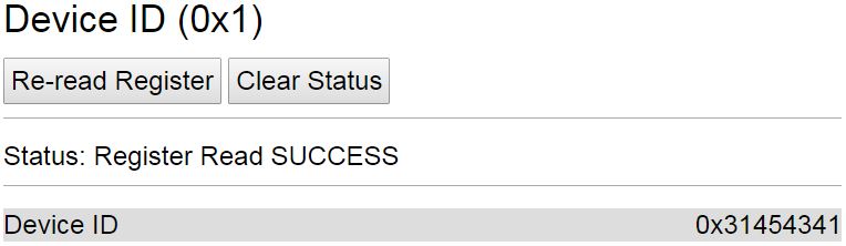
Recently, I had bought 2 TPS65982 EVM boards. The firmware is exectuing perfectly fine and I am able to read the registers as well using the GUI utility provided. I want to test the data routing capabilities of the EVM. How can I emulate the data for USB 2.0/3.0/3.1 so that i can observe the data routing on TPS device? Kindly provide some insights on doing the same.

  • Hi Fadil,

    Sorry for the delay, I have moved this to the USB forum for assistance.
  • Fadil,

    The TPS65982-EVM boards do not have the SuperSpeed data pairs routed for DisplayPort or USB3. For this EVM we were showing the power and FW capabilities of the device when it was 1st released to market around this time last year (2015).

    For the USB2.0 or SBU1/2 pairs it would pretty easy to test the signal routing capability with a multi-meter by "Ohm'ing" out the connections, i.e. performing a short test across the switch. For USB2.0, you can measure from C_USB_TP/TN to USB_RP/RN when the Type-C cable is plugged in right-side up and from C_USB_BP/BN to USB_RP/RN when the cable is upside-down. When the DisplayPort Alternate Mode is entered, you can measure from SBU1/2 to AUX_P/N or from SBU1/2 to AUX_N/P, depending on cable polarity.

    Our latest design, the TPS65986EVM, has a pair of Expansion cards with USB3 and DisplayPort receptacles on it (Source and Sink boards), which allows you to test the full system from a Legacy PC to a Legacy Monitor (DisplayPort connector as opposed to Type-C). You can also connect the USB3 receptacle of the Legacy Laptop to a USB3 Flash Drive on the opposite end.

  • Thank Mr.Brian for your valuable inputs. Is it possible to have a closer look at the source code of the PD negotiation process? I wanted to know the sequence for the PD contract negotiation. I would like to know the following:
    I tried to communicate with TPS65982 EVM over I2C with a PIC MCU. From the datasheet of TPS device on page 66 I understand that there are 3 parameters which determine the I2C address. I would like to know how the python script is modifying the voltage levels on these pins (OTP, DEBUG_CTLX ) so that I can fix the I2C address. I tried addresses 0x38, 0x00, 0xFF, 0x3F. how can I program the I2C address with a separate MCU?
  • Fadil,

    The Python script is not modifying the Voltage on the DEBUG_CTL1/2 or I2C_ADDR pins. They are fixed in HW on the PCB. The default 7-bit address is 0x38 and it should work if you are connected to the I2C1 bus (DEBUG_CTL1/2 voltage is ignored and value set to '1' for I2C Port 1) because I2C_ADDR is pull-down to GND with a 0-Ohm resistor on the TPS65982-EVM.

    If you are connected to the I2C2 pins, DEBUG_CTL1/2 have an effect and need to be considered. If DEBUG_CTL1/2 are pulled-down to GND, the resulting I2C Slave address for I2C2 Port will be 0x20

    You can modify the setting in the script by changing the "DEVICE_I2C_ADDR " variable's value in the Config.py Python script.

    In the TPS65982-HIUTILITY GUI, you can change the Address in the Configure tab then click "Save Settings as Default". This will automatically overwrite the value in the Config.py file.

    I make a habit of checking my I2C address in the GUI and reading the FW settings on the chip before I start modifying the Python scripts to perform complex functions.

  • Ok Brian, I will recheck it & get back to you. Actually I had already tried reading the register values with a separate MCU running I2C with address 0x38 for which the TPS device was not acknowledging. Now I am using a multi master set up where I have a PIC MCU and Aadvark I2C adapter. From the software the values are coming properly but when I am using the Aadvark GUI the registers don't throw out values with the same address 0x38. 

  • Fadil,

    If you are still having issues with either the GUI or the Command line version of the TPS65982-HIUTILITY, please attach a screen shot of an error message so I can assist you further.
  • Hello Brian,

    Thank you so much for your strong support. Finally I was able to read the registers using the PIC MCU:     

                                  Fig 1: Result on TI Utility tool

                                    FIg 2: Results obtained in PIC MCU (MPLab)

    Just in case, I have attached the results obtained. Kindly ignore [0] byte.

    Could you also please tell me a method wherein I can generate continuous stream of any BMC coded messages on the CC line? Any message would suffice as I am only looking forward to extract the Eye-Diagram on the scope.

    PS: With the command line version of the tool, I am not able to do an Aadvark scan. It is always referring to the FTDI drivers. Just to know, is there any way to do a Aadvark scan on the command line version?

    Thank you,

    Fadil Luquman

  • Hello Brian,

    Is it possible to get the source code for the TPS65982 device and not the bin file? I want to know the sequence in which the PD negotiation happens.
  • Hello Mr. Brian,
    I had requested for information regarding the firmware of your USB-PD. Could you please tell me if it's code has been released or it is still under optimization? Would you be able to provide any reference code, firmware flow or pseudo code regarding the same?
  • Please download and install the TPS6598X-CONFIG Tool. This tool allows you to configure the TPS65982 FW based on your specific application.

    The FW is stable and released, it has passed USB I/F Certification for USB-C/PD, and the Config-Tool allows it to be configured, but the source code will not be released for customer's to modify. Since the PD Policy Engine is certified, if customers modified the source code then the PD Policy Engine could be made non-compliant or important safety features could be disabled.
  • Yes Mr.Brian, I am aware of the configuration tool. I neither intend to configure nor modify. I just want to know the FW flow of the USB-PD. I just want it for reference. Not the actual code, any pseudo code would be enough.
  • Fadil,

    The FW User's Guide describes the flow and behavior of the TPS65982: www.ti.com/.../slvuah7

    There is no pseudo-code available for you to inspect.
    If you have questions on a particular section of the FW User's Guide, please refer to a specific section and page number so we can answer your question in more detail.