This thread has been locked.

If you have a related question, please click the "Ask a related question" button in the top right corner. The newly created question will be automatically linked to this question.

TCA6507 used to control light intensity

Other Parts Discussed in Thread: TCA6507

Hi,

I'm currently working on a project wherein I will be using the TCA6507 to control the light intensity of an LED. I will be using LabVIEW for this. I know that in order to control the intensity, I will be dynamically varying the duty cycle of the signal.

I just got confused with the statement in the paragraph below:

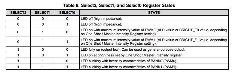
1) What does it mean that the seven output can be configured into two banks of outputs (BANK0 and BANK1)?

2) How is PWM0 related to BANK0? And PWM1 to BANK1.

Also, can you give me insights, what's the first action to take, to start setting the intensity of an LED?

Thanks,

Jude

  • Hi Jude,

    Thanks for the question. I've provided answers below:

    1) What does it mean that the seven output can be configured into two banks of outpputs (BANK0 and BANK1)?

    Let me first start by explaining the SELECT registers. In the TCA6507, you have the option of writing to 3 registers (SELECT0, SELECT1, and SELECT2). Each bit of these three registers corresponds to a specific Port on the device which controls a specific LED. Please refer to the attached table to see how configurations of bits within the 3 registers change what the LED will do. For example, bit 0 will correspond to P0 and what those bits are set to will set the LED in a certain state.

    Now in regards to BANK0 and BANK1, think of them as assignments for which LED will be placed into. For example, LEDs P0 - P4 can be "Controlled" by BANK0 and the rest in BANK1. It is merely a control BANK to have various blinking.

    2) How is PWM0 related to BANK0? and PWM1 to BANK1?

    This will apply to both BANK0 and BANK1.

    PMW0 relates to BANK0 in regards with the PWM0 controlling the light intensity of the LEDs. 

    Quoted from the Datasheet, "The Maximum Intensity registers must be written to for setting the intensity of the LED. This register has eight bits – top four bits for BANK1 (or PWM1), and bottom four bits for BANK0 (or PWM0). This register can be written to after sending data to the Second Fully-OFF Time register (see Table 20). The Maximum Intensity register has a default value of 15 (1111), which translates to 100% brightness (see Figure 19 and Table 5)."

    This should help you get started with setting the intensity of an LED.

    Thanks,

    Siby

  • Hi Siby,

    Thank you very much for the answers. For the first and second question, I'm already clear with that. Can you expound more on how to get started. I believe the Maximum Intensity registers must be written to set the intensity. But it's not very clear to me.

    For my project, this is my scenario:

    First LED is off, and in my LabVIEW program I have a knob control. I will slowly turn the knob until it reaches the maximum intensity. Wherein, the Maximum Intensity register for the TCA6507 has a default value of 15 (1111), which translates to 100% brightness.

    Can you guide me what are the different registers that I should write to? Let's say what will be the register that will have the 0000 value (off)? And then next, until it reaches the maximum of 1111.

    Also will I not be using the Select0, Select1 and Select2 registers for controlling the intensity?

    Thanks and Regards,

    Jude

  • Hi Jude,

    I will elaborate on the process to get you up and running. Please give this a try and let me know if you run into problems.

    The device, TCA6507, is an LED driver that acts off specific ports that control the LEDs. To use one of the ports, you must use the Select[0-2] to ensure that your LED is turned on.

    The intensity of each bank of LEDs can be customized by programming six registers: Fade-ON Time, Fully-ON Time, Fade-OFF Time, First Full-OFF Time, Second Fully-OFF Time, and Maximum Intensity registers. 

    Please take a look at the Control Registers below to get an idea of what registers are available. Below all the control register descriptions in the datasheet are the individual registers and the descriptions of how to control the intensity of light. Also please take note of the initialization register (0x0A) which determines whether to initialize each PWM and provides a starting point of the LED intensity cycle for each bank.

    Thanks,

    Siby

  • Hi Jude,

    May I know how does the you Labview VI look like? I using the TCA6507 to control the LED light intensity too. I just no idea how to implement on LabVIEW. Thank you for advance.

  • Hi Siby,

    I started to work on this already, however I run into some problems. I have a question, why was the address byte set to 0x89, when in fact, it is a write operation, for write operation (Address bits)(0--> Write), it must be 10001010-->8A.

    Also, can you provide an example table for me to start the writing process to control the intensity, which is similar to this: This is the application example from the datasheet for the blinking pattern of LEDs. Can you guide me what must be the first byte to send, and then second until the next, in order to control the intensity of the LED.

    If you can provide me any example projects before even not using LabVIEW to control the intensity of the LED using this TI Led Driver, would be much appreciated.

    Thanks, 

    Jude

  • Hi Jude,

    Thanks for the follow up. I'll look to see what I can dig up for you.

    Thanks,

    Siby

  • Hi Siby,

    Good day to you!

    Did you find something relevant that can be used as reference? If possible can you provide an example table for me to start the writing process to control the intensity, which is similar to the table I sent on my last email. Can you guide me what must be the first byte to send, and then the second until the next, in order to control the intensity of the LED.

    If you can provide me any example projects before even not using LabVIEW to control the intensity of the LED using this TI Led Driver, it would be much appreciated.

    Hope to hear soon from you.

    Regards,

    Jude
  • Jude said:
    Hi Siby,

    Good day to you!

    Did you find something relevant that can be used as reference? If possible can you provide an example table for me to start the writing process to control the intensity, which is similar to the table I sent on my last email. Can you guide me what must be the first byte to send, and then the second until the next, in order to control the intensity of the LED.

    If you can provide me any example projects before even not using LabVIEW to control the intensity of the LED using this TI Led Driver, it would be much appreciated.

    Hope to hear soon from you.

    Regards,

    Jude

    Hi Jude,

    Do you have an example vi how does the LED driver implement on the LabVIEW? 

    Thanks.

  • Hi Siby,

    Do you have any updates regarding my query. If you could send some basic examples for me to try controlling the light intensity.

    Hi Jin Ooi,

    Sorry, I just responded now, since I was working on with another project. I will be working on this already. Have you started creating your own VI for controlling the LED Driver?
  • Do you have any updates regarding my query. If you could send some basic examples for me to try controlling the light intensity.
  • Hello Jude,

    Siby is no longer with our group.

    I'll take this request over. Please refer to section 9.2 in the datasheet () as I gave a fairly detailed example about how to program a light blinking pattern.

    If you only care about changing intensity, then you just need to change the maximum intensity register only as outlined in my example in the datasheet (register 0x08).

    Feel free to ask more questions if you don't understand an aspect of it.

  • Hi Jonathan,

    Thanks for your reply. If you can provide me a sample table similar to this, which shows the bytes I need to write to the registers.

    I need to control the intensity from 0-100%, please advise me the first byte to write, the second byte, third byte and so on. It would be best if you outline it the same way as the image above.

    Regards,

    Jude