This thread has been locked.

If you have a related question, please click the "Ask a related question" button in the top right corner. The newly created question will be automatically linked to this question.

TCAN33x vs other CAN drivers

Hello experts, 

We currently are using the TCAN33x series for a 1Mbps 40m CAN bus application. I am new to this project, and I do not believe much time was spent on researching these parts. Not that I believe they are bad parts, but I have been reading the SLLA270 CAN design document, and I’m not convinced that they are the exact part we’d want for our setup.

We have a system that has these specs:

Total desired length: 40m

Desired data rate: 1 Mbps

17 total devices on the bus

Stub length: .5m   (initially we wanted 1m, but I believe this is limited by the rise time of the TCAN33x in our system, measured to be 25 ns)

Cabling: Devicenet cables from Molex, or 22/24 cable from Belden, 120 ohm terminated at the ends of the bus (no split terms or anything exotic)

Transceiver: TCAN33x family (332 or 334, depending on the application) running at 3.3V


The most important specs are the first 3. We can compromise on drop length, I’m currently limiting it to 1/3m, but I think we could go to .5m pretty easily. Right now, we can only get the bus to run at 500 kbps reliably with no errors. If we go to 1 Mbps, then we get lots of passive and active errors (though we still do get data to some degree as well). The errors eat up the bus BW essentially, and I’m sure it’s no good to be running with a lot of errors anyway.

 Is there a suggestion from TI on what CAN transceiver you would suggest for this bus setup? Maybe the TCAN should work, but there might be a better option? Would 5V help us in this situation? We’ve had an internal debate about that, but of course, we’d have to add level shifters to interface back to the AM335x.

 Any help here would be appreciated. We believe that we can do our proof of concept with the current bus, but for production we likely need to get to 1 Mbps.

Ed Wood

Sr. EE, Product Innovation Center

Nytec, Inc.

  • Hi Ed,

    Thanks for clearly summarizing the issue. I do believe that 1 Mbps should be achievable with TCAN33x in this application, so let's see if we can figure out what is going wrong.

    Do you think we could take a look at the CANH and CANL waveforms at the input to one of transceivers to get a better idea of what might be impairing the bus (e.g., stub reflections, ringing, slow edges, excess loading, noise coupling, ground offsets, etc.)? That would be helpful in narrowing down what exactly could be introducing errors.

    Besides the transceivers and the termination (120 Ohms at each end between CANH and CANL), are you using any other circuitry on the CAN bus (e.g., for noise filtering, transient protection, etc.)?

    If you were interested in evaluating a 5-V device you could try TCAN1042V or TCAN1051V. These devices have a logic supply input that you could tie to 3.3 V to set the RXD and TXD logic levels without requiring a level shifter. I don't have any reason to think that using a 5-V transceiver would improve anything, though.

    Regards,
    Max
  • Thanks for your answer Max. I'm glad you think that the TCAN33x can get to the 1Mbps in our application. One thing I may not have mentioned, I can run at 1 Mbps with shorter distances and less loading. For instance, if I have 4 loads on the bus, and 20m of cable, the system does run at 1 Mbps, though the signal quality is not great (we are using the CAN-Bus Tester2 from GEMAC to evaluate CAN bus signal quality and watch for active/passive errors).  I will work on getting some scope shots of the working and non-working cases and upload them.

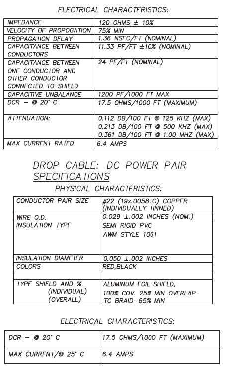
    As for the other circuitry on the bus, the only things we actually have loaded are a CDSOT23-SM712, which has 75 pF of capacitance on it.  17 devices would make it 1.275 nF max capacitance.  The cable specs are pretty good I think, see below:

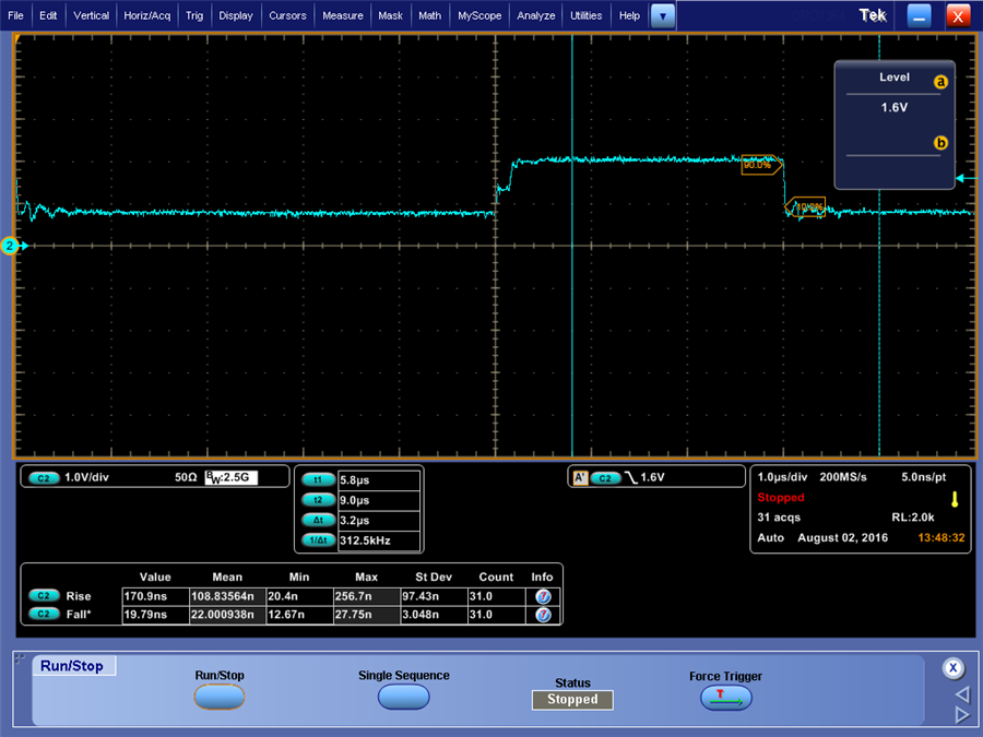
  • I have some obtained some scopes shots of the CANH and CANL lines. The scope setup is a little overkill but it was the easiest one to get a hold of.

    Scope: Tek SPIO7354 3.5 GHZ, 40 Gs/s

    Ch1: TDP3500 3.5 GHZ diff probe

    Ch2 and Ch3: TAP2500, 2.5GHz Active probe

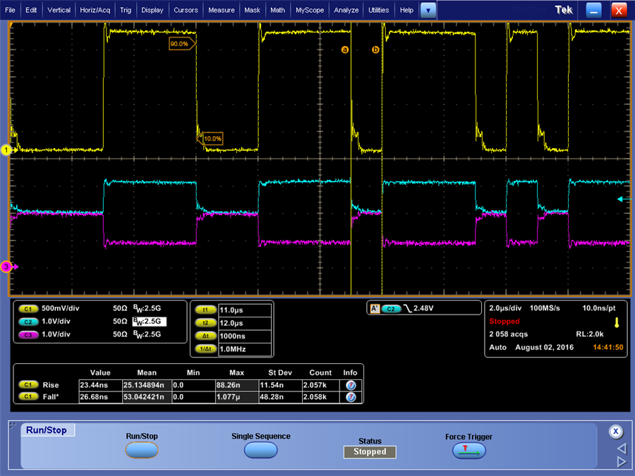
    This is a shot of normal CAN bus traffic (yellow is DIff, blue is CANH, purple is CANL):

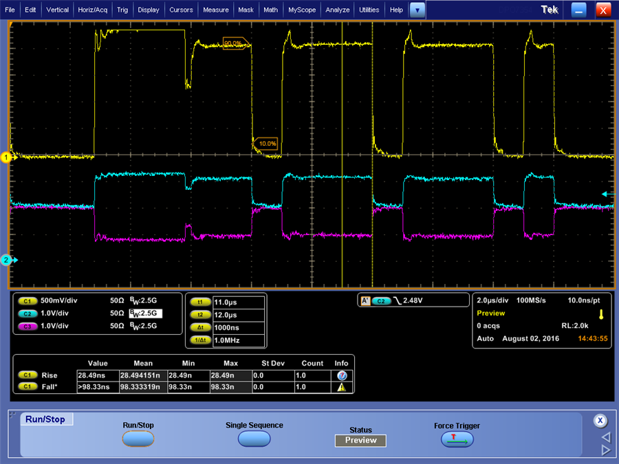
    Looks relatively fine. Then I caught this shot:

    So either a runt pulse or a reflection showing up there, with the sharp edge, looks more like an intentional beginning of a pulse to me and not a reflection.

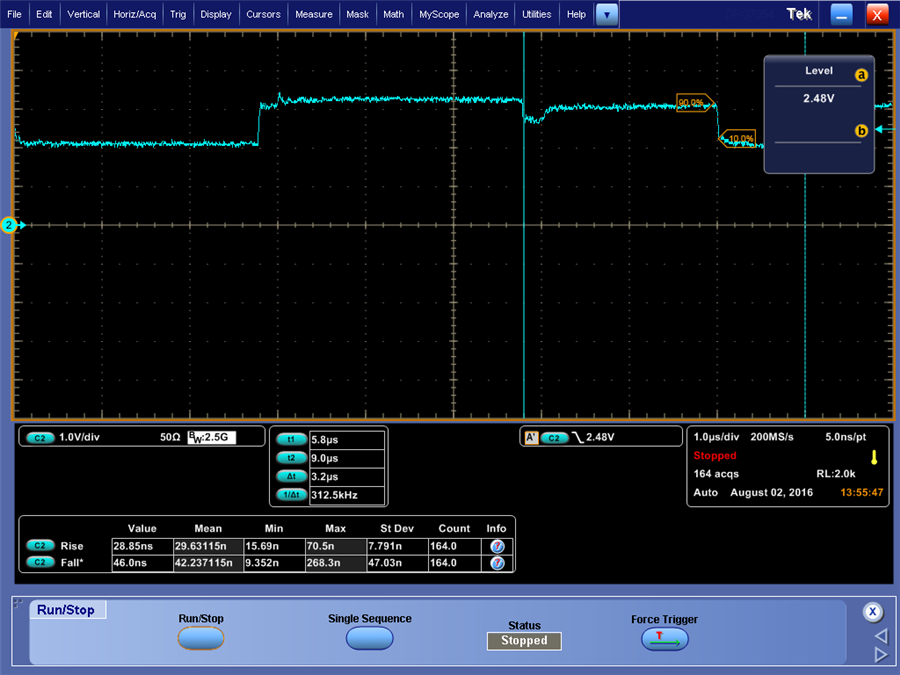
    This was the CANH single ended weird pulse: 

    And this was the CANL shelf edge:

    The last image looks more like a transmission line impedance issue. I have measured the term resistance on the CANH/L lines, and it's 61.2 ohms, pretty close to what it should be.

    Any ideas from looking at these scope shots?

    Ed

  • Ed,

    It's tough to say. When the dip is close to the edge (as in your last picture) it does look like a reflection that you might expect from a termination mismatch, but it could also be the same runt pulse that is showing up later during the dominant periods. (I would guess it's the second option in this case given that the total termination resistance is close to 60 Ohms and the stub lengths do not sound overly long.)

    Was the overall bus configuration (number of nodes, stub lengths, etc.) the same for all of these scope captures? What needs to change in order to get the issue to show up?

    If you wanted to check more into the runt pulses, you should be able to probe the TXD pin of whichever transceiver is sending the data during this test. If you see TXD toggling then you would at least know that this isn't something resulting solely from the physical layer (cabling architecture, noise coupling, etc.).

    Have you looked much into the configuration of your controller? I mention this since the analog signals look mostly OK (with the exception of the runt pulses - they are the right amplitude, transition at the right rate, etc. If the timing parameters of the controller aren't optimized for this bus/speed, though, it may explain the error rate.

    It looks from the waveform shown above like the "dip" is following the arbitration period of the CAN frame. (This period has higher signal amplitude due to multiple CAN drivers outputting a dominant level at once.) Is this always the case, or do you ever see it occur at different times? If it always follows arbitration it may help give a clue as to what is going wrong.

    Max
  • Hi Max, thanks for you reply.  My bus setup is this:

    4 loads

    1/3 drops

    overall backbone length of 20m

    1st load was basically at 0m distance. The other loads were at +1m, +3m, and +19m.

    I did have 10 stubs on the bus that were not terminated with loads.

    I will look in to your question about the config of the controllers (that had crossed my mind as well after seeing the signals, I thought in general they looked pretty good).

    Ed