This thread has been locked.

If you have a related question, please click the "Ask a related question" button in the top right corner. The newly created question will be automatically linked to this question.

DP83849IF

Other Parts Discussed in Thread: DP83849IF, SN65LVELT22

Hi 

We want to develop a fiber-to-copper media converter product by means of DP83849IF chip.

in the evaluation board of the chip (part number: tidu510a) there is a HFBR-5803 transceiver which receives the SC type fiber and convert it to electrical signal.

However we want to have a SFP connector on our board so we can receive different types of fiber inputs (GPON, etc.) my question is that is it safe to replace the HFBR-5803 with a SFP interface? is it compatible with the chip itself? is there any other precautions that we should consider?

thanks in advance

  • Hi Mike,

    That is completely OK, but please review the DS of the SFP before finalizing the circuit. Some SFP modules are DC and some are AC coupled. If you want, please send the SFP you plan to use and I can review it.

    Kind regards,
    Ross
  • Ross,

    I'm very thankful for your answer,

    Look, the point is I want my circuit to work with as many SFP modules as possible, so our product will be compatible with various fiber networks.

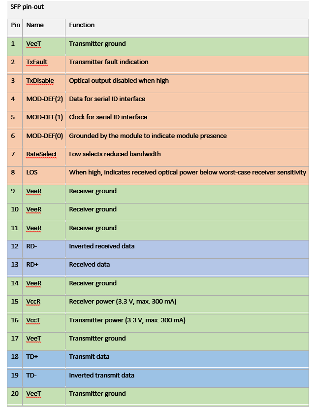
    My main question is that as you already know an SFP connector has 20 pins  as shown below; I will connected the green highlighted pins to VCC and GND on board respectively, and the blue rows are our data. However I'm not sure about the orange highlighted rows. Should I pull up (down) these pins? or I should consider other things? 

    Regarding what you said on AC/DC coupling what should I check in the SFP module? Do you have a reference design which supports the majority of the current SFP modules in the market?

    Regards.

  • P.S.: in some application notes that I've read it is mentioned that MOD-DEF(2,1,0), TX-Fault and LOS should be pulled up to VCC, and TX-disable is already pulled up within the module. is that correct? if yes, then should I connect these pins to any pins of my Host chip (i.e. DP83849IF) or just pull it up and leave it there?! Also what should I do with RateSelect pin?
    Also, I have read somewhere that the LOS pin should be connected to FXSD on DP83849IF by means of a level shift (e.g. SN65LVELT22), is that correct?
    sorry for my too many questions, I'm a little confused.
  • Hi Mike,

    No worries, this stuff can get pretty confusing at times so I understand.

    Here are the pins you are not sure about:

    2. TX_Fault
    3. TX_Disable
    4. MOD_DEF(2)
    5. MOD_DEF(1)
    6. MOD_DEF(0)
    7. Rate_Select
    8. LOS

    TX_Fault can be left unconnected if you do not want to use it.

    TX_Disable when pulled down will enable the transmitter and when disabled or pulled high will disable the device. If you do not plan to have a controller dictate operation, I would suggest you pull this down so that the transmitter is not disabled, but this is up to you.

    MOD_DEF[2:0] these are for communicating with the fiber module, up to you if you want to use them, but if not used, you can leave them unconnected.

    Rate_Select is not connected so you can leave it unconnected.

    LOS will indicate loss of signal. This usually requires an external pull-up to VDD. Logic '1' indicated loss of signal and a '0' indicates normal operation. For this you can use the FXSD pin, otherwise you can leave it unconnected since the PHY supports Far-End Fault detection.

    For the RD/TD pins, I would suggest you use 0.1uF isolation caps. Put 50 ohm terminations between the PHY and caps on the TD pins. Put the 130/80 ohm terminations on the RD pins between the PHY and caps.

    Kind regards,
    Ross
  • Thanks again for your comment Ross,

    What is important for me is the final Ethernet (copper)  signals are valid and have continuous value. You are saying that "if you want to use them..." the point is that I don't know if I "need" to use them or not? If I don't use these signals is it possible that the module stops working (e.g. if an interrupt or request from SFP module is left unanswered by the PHY). As long as this is not the case I am OK leaving these pins floating or pulling them up/down as you stated.

    About the isolation, there is an application note named (snlr002) which contains the schematic of the evaluation board, in page 5 of that document the isolation caps are only inserted for TD pins and RD pins are connected directly. I think that this is dependent on the SFP module, right? however you recommend to use isolation caps for both TD/RD pairs.

    Another question is that I want to use strapped mode and I understand that in Media-conversion mode both ports must be in SCMII or RMII mode. If I use RMII mode, I should use an oscillator and 50MHz crystal is not supported, so I decided to use SCMII mode. Is there any possible limitation or shortcoming in using SCMII mode with strapping? 

    My main concern for using RMII mode is the oscillator thing which adds to the complexity and BOM as well as its accuracy is a concern which may force us to use the "elasticity buffer" that needs programming the registers which we avoid.

  • Hi Mike,

    The question of whether or not the SFP module ceases to operate if a MOD_DEF signal is unanswered is a question for the SFP manufacturer.

    The isolation used on the reference design is dependent on the SFP used as you pointed out. Due to the nature of the drivers used, no isolation was needed for the RD pair. It is recommended to use isolation for other SFP modules as Ross pointed out.

    For the purpose of a media converter, if you are not including a MAC layer device, using RMII and SCMII mode is essentially interchangeable. As you pointed out, RMII would cause added BOM cost, layout complexity, and board space.

    As such it is advisable to use SCMII mode of operation. There is no limitation to strapping to use SCMII mode verse RMII.

    Best Regards,