This thread has been locked.

If you have a related question, please click the "Ask a related question" button in the top right corner. The newly created question will be automatically linked to this question.

use SN65HVD379DR for FW update to STM32F051R8T6TR

Hello Everyone,

I'm using a pair of SN65HVD379DR RS485 chips to communicate between 2 micros on separate PCB's. The communication is clean and works great after firmware is loaded onto both boards. A requirement of this control system is the smaller micro must be updated by the main control board as it is inaccessible to the end user. 

The micros were originally communicating directly with each other, but we had noise issues, so we switched to RS485. The communication now works great in normal use, but the firmware now fails to update via the main control board!

Some additional Info:

  • Micro on daughter board requiring FW upload is STM32F051R8T6TR
  • Daughter Micro is set into boot mode by powering the PCB down (power is supplied by main control board), switching the boot signal, and powering back up. 
  • bypassing the RS485 chips on testbench results in successful FW upload
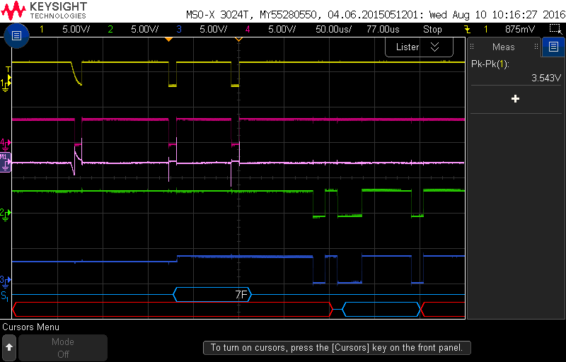
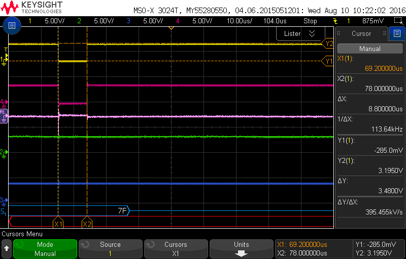
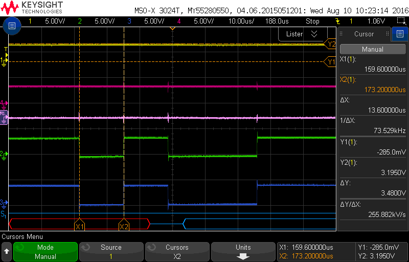
  • micro being updated utilizes "autobaud" when in boot mode. signal sent back to micro performing upload is slower than what is sent by main control board.

Does anyone have a suggestion on further troubleshooting, crosses that can perform this function, or any other ideas? I have been hunting this issue down for a while with little success. 

Thank you in advance for your time.

  • Hi Paul,

    Since communication works normally (once firmware is loaded), to me it would make sense to look deeper into the autobaud issue and try to figure out what is going wrong there. How was autobaud implemented before, and how did that change with the addition of an RS-485 transceiver?

    Max
  • Hi Max,

    I captured the waveforms of the control/UI com’s during failed update, treating the RS485 coms as a black box


    • 1(YELLOW): control TX
    • 4(RED): UI RX
    • 2(GREEN): CONTROL RX
    • 3(BLUE): UI TX
    • M1: MATH FUNCTION [CONTROL TX – UI RX]


    Also attached are measurements of the frequency. The control TX has a slope on the first bit that is always present, but the RS485 looks to be filtering this out. UI TX (BLUE) voltage raises slightly, but does not show on the control board RX(GREEN). The control board sends the correct upload start byte (F7), and the UI returns the correct acknowledge byte (79), but the baud is slower. The baud rate of the control board is always ~1.69x the baud returned by the UI board. We have tested different baud and come up with the same ratio. Next I am going to bypass the RS485 to show the upload acknowledgement when succesful.

    For the 3 images attached, the first is the entire communication sequence. The second is the control TX frequency measurement (115.2Kbaud). The last image is the UITX (~74Kbaud)

  • Hi Paul,

    Forgive me for my ignorance here (my knowledge is primarily on the transceiver devices), but how would you expect these waveforms to look in a fully functioning system? It looks to me like the data is making it across the link intact - is that the right interpretation? How would this differ if the RS-485 chip were bypassed?

    Regards,
    Max
  • I will have time tomorrow to get the scope, but i expect the acknowledge from the UI to be at the same frequency as the 7F from the control, 115.2Kbaud. hopefully it will reveal more.