This thread has been locked.

If you have a related question, please click the "Ask a related question" button in the top right corner. The newly created question will be automatically linked to this question.

SN65176B failsafe biasing and terminating resistors

Dear all,

I have several questions about failsafe biasing and termination resistors.

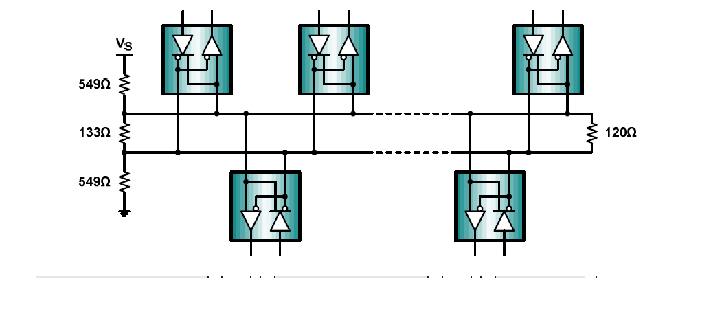
1. What are Min and MAX value for fail safe biasing resistors?

At attached app note, 549 ohms is recommended.

At Modbus guide line, The values are between 450Ohms and 650Ohms.

Could you explain why  values are between 450Ohms and 650Ohms at Modbus?

 What problem is in RS485 network system if fail safe resistor is below 450 Ohms?

 2.   What are correct termination resistors values?

  if at master side, termination resistor value is 120Ohm,  Can we use 130Ohm  at slave end?

At Modbus guide, 150Ohm is recommended. Modbus_over_serial_line_V1.pdf

MODBUS over Serial Line
Specification & Implementation guide

"The value of those resistors must be between 450 Ohms and 650 Ohms. 650 Ohms resistors value may allow a higher number of
devices on the serial line bus."


"Line termination may be a 150 ohms value ( 0.5 W ) resistor.
A serial capacitor ( 1 nF, 10 V minimum ) with a 120 Ohms ( 0.25 W ) resistor is a better choice when a polarization of the pair must
be implemented (see here after).
In a 4W-system, each pair must be terminated at each end of the bus."

 Passive Failsafe for an Idle Bus.pdf


  • Hi Philip,

    The values of the pull-up and pull-down resistors should be chosen based on how large of a differential offset is desired when the bus is idle (not driven by any active transceivers). The goal is to make sure that the high-level threshold of all the receivers on the bus is reliably exceeded even in the presence of differential noise in the system. Larger resistances will give less offset, and smaller resistances will give more offset.

    At the same time, it is important to make sure that the equivalent resistance of the termination network matches the differential characteristic impedance of the cabling used. A common target for RS-485 is 120 Ohms. Since the extra pull-up and pull-down resistances will lower the effective resistance at the termination network, often the differential termination resistance is increased in order to compensate. You can use the formula Req = RT || (2*RFS) to compute the equivalent resistance, where Req is the equivalent resistance, RT is the differential termination resistance, and RFS is the failsafe resistance.

    One disadvantage to using very low resistance values is that it becomes more difficult for a transceiver to overcome the larger offsets when driving a "low" level on the bus. It also can increase the amount of loading on the bus (i.e., lowers the overall resistance from the A and B lines to ground), which could reduce the maximum number of nodes that would be achievable.

    Regards,
    Max