


Other Parts Discussed in Thread: TPS65982, HD3SS460, TPS65982-EVM
I have a customer who is seeing the TPS65982 “hiccup” even though the current being sourced from the part doesn’t reach the 3A current limit. I am not sure if this is a firmware or software issue but please read the customers comments below:
Did you use the software/ firmware tools to create the firmware template?
Yes I used the “TPS65982 Application Customization Tool” to create the firmware template and I used the default template “TPS65982_HD3SS460_UFP_Full_2_8.tpl” for the project because it support Power and data sink only. Also the firmware base image is based on “tps65982_0001.11.02_lowregion.bin”
Are you sure that the TPS65982 is in the proper mode? Are the other modes that you are using it in operating properly or have you seen issues with their operation also?
I did test the circuit with a digital load equipment and setup the load current of 3A and I can see the controller auto-negotiate to 20V power input from USB type-C power supply without hiccup.
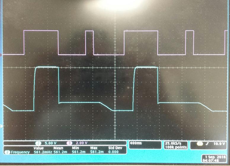
Now I adjusted the load to have the inrush current down about 1.5A but the TPS65982 still hiccup with P5V Overcurrent Event show on GPIO #14. I attached the waveform of the VBUS of the USB Type C input (blue channel # 2) and the GPIO # 14 mapped event of P5V Overcurrent Event (purple channel @# 3 – active low) so you can see the problem. Is there other way I could troubleshoot the problem on the controller. I believe that some condition that tell the controller to shut down. Also during the hiccup I cannot read the registers or communicate to the controller through I2C so I think the controller is in some kind of reset.
Here is the schematic with TPS65982.
(I can send to you off-line if you need it)
I already did the following mod:
1. Install 0 ohm resistor to R742 for master
2. SW2 setup ON, ON, ON, OFF which is conf0 = Low, conf1= Low, conf2 =Low and GPIO5_HPD = High
3. I connected the I2C port 1 and SPI flash to the AARDVARK I2C SPI adaptor to use the program to load firmware and control I2C
4. Jumper J41 to pin 2 and 3 for bootup from SPI flash.
Can you explain the soft start function as explained in the data sheet (Section 8.3.3.16)? Is the soft start function only applicable in a “sinking” application? The customer’s application is sourcing the current. Does it only work up to 5.5V? Does this mean if the customer is sourcing 20V that the soft start circuit is not active?
Please let me know if you need further information from the customer.
Thanks for your help with this!
Richard Elmquist


