This thread has been locked.

If you have a related question, please click the "Ask a related question" button in the top right corner. The newly created question will be automatically linked to this question.

DP83867CR frame loss and CRC error with certain frames sizes

Other Parts Discussed in Thread: DP83867CR, DP83867IRPAP-EVM

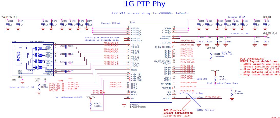
We have a design with DP83867CRRGZR.

We see an incomprehensible behavior with the DP83867CR, we see frame loss and CRC error in the ingress traffic but only with some frame sizes.

In order to debug the issue, we enable the PHY in line (reverse) loopback without forwarding to the MAC interface.

We connect the Ethernet MDI interface to a Spirent testcenter and send 65 byte frames with 95% load into the DP83867CR and capture the output.

With 65 bytes frames we see frame loss or CRC on about 1 frame out of 500,000 frames.

We don’t see any error with 64 and 66 bytes frames.

We have verified the DC level and noise on the power supplies, and in order to insure we doesn’t have an issue with DC drop we have tried increasing all the supplies with 50mV.

Do you have any idea what can cause this behavior in DP83867CR?

  • Hi Sune,

    It is indeed a peculiar problem and we haven't seen this before. Could you let me know more information regarding the test setup.
    What is the cable length?
    What is the payload type? Random data, fixed data etc.
    How many samples were tested? Do they all show the same problem?
    Can they test thier board for 1G Ethernet Compliance?
    What is the clock source? Does it have +/-50ppm frequency tolerance?

    -Regards,
    Aniruddha
  • What's your clock source?  If it's an oscillator, maybe you have an issue with jitter?

  • Hi Aniruddha,

    The issue seems to be independent of the ethernet cable length and whether the PHY is in master or slave mode. But it need to be in 1G mode.

    I have tested with PRBS payload and fixed payload and the issue is not dependent on the payload.         

    We notice some CRC errors on our systems, so I began the debug on only one system. I have only verified the 65 byte issue on one system. I will verify whether the other system also have the issue with 65 byte frames with 95% load tomorrow.

    The 25 MHz clock is from a TCXO. I have tried to change the clock source to a SI5344 but I did not see any change in the PHY behavior.

    I have verified the clock output signal from the PHY in order to verify the clock inside the PHY.

    Regards Sune

  • Hi

    I have verified that the issue is also exist on another board, so it is unfortunately not just a single device defect.
    I have measured the jitter on the output clock from the PHY. Thereby I can measure the reference clock that the PHY see.
    The 25Mhz clock out of the PHY has a Cycle-Cycle jitter RMS jitter of 34 ps and N-cycle jitter RMS jitter of 23 ps, see plot below.
    I have also measured the receive clock for Channel A and I can’t see any issue with the receive clock. A plot of the measurement is bewlo .
    I tried to measure the error rate with difference frame size, see list below. 
    Notice the pattern in the frame size where I see the issue:

    - 65 Byte frames bit error rate  3.0 x 10^-9
    - 73 Byte frames bit error rate  2.2 x 10^-9 
    - 81 Byte frames bit error rate  3.6 x 10^-9
    - 89 Byte frames bit error rate  3.0 x 10^-9
    - 97 Byte frames No error

    Regards Sune

  • Hi Sune,

    As per your scope pictures the oscillator frequency is 25.02MHz which violates the +/-50ppm requirement on the clock. Will it be possible for you to share the schematics so that we can have a closer look?

    -Regards,
    Aniruddha
  • Hi Aniruddha 

    I also see the 65 bytes frame issue on the Texas Instruments evaluation board “DP83867IRPAP-EVM”.

    Below are the MDIO commands send to the board:

    Notice, in my setup I see the issue regardless of the loopback.

    Please check my setup below and comment on next step in the debug process.


    #Reset all registers (and not just IEEE registers using BMCR bit15)

    MDIO_write(0x001F, 0x8000)

    Sleep 100ms

    #Enable Auto-Negotiation and FDX =1

    MDIO_write(0x0000, 1<<12 | 1<<8)

    # ANEG_RESTART=1

    MDIO_write(0x0000, 1<<12 | 1<<9 | 1<<8)

    #Setup PHY for normal operation and auto MDIX

    MDIO_write(0x0010, 0x5048)


    #Enable loopback

    MDIO_write(0x00EF, 0xE720)

    #Soft reset after changing LOOPCR

    MDIO_write(0x001F, 0x4000)

    #Enable reverse loopback (MDI RX to TX)

    MDIO_write(0x0016, 0x8 << 2)


    Regards Sune


  • Hi Sune,

    A few comments about the register settings, Auto-negotiation and Auto-MDIX are enabled by default so writing to register 0x00 and 0x10 is not required. 0xEF is not a valid register, I think it might be a typing error with register 0xFE. Also, writing to register 0xFE is not recommended for Reverse loopback. For reverse loopback in 1G speed, only write 0x20 to register 0x16.

    I tried to replicate your setup with the Spirent Smartbits in our lab and test for 65 byte packet (61 byte data, 4 byte CRC) and 69 byte packet (65 byte data and 4 byte CRC). Both the test showed error free results. I used the DP83867IRPAP-EVM for this test.

    Lastly, what IPG setting are you using for the test? The lowest IPG supported by DP83867 is 96nsec.

    -Regards,
    Aniruddha
  • It seems like the issue is caused by the IPG occasional is below 12 byte.

    The Ethernet package generator vary IPG, in order to match the requested load of 95%, but occasional the IPG is below 12byte.

    The 1000Base-T receiver must accept IPG of 8 Byte according to IEEE 802.3 chapter 4.4.2 Note 3.

    It seems like the DP83867 has an issue with IPG below 12 byte.

    In our current use case for the DP83867, we can live with the IPG issue in DP83867, but please consider to make an errata as the PHY it is not fully IEEE compliant and it is expected to see CRC error on random test if the IPG is not locked.

    Regards Sune

  • Do you agree with my conclusion?
  • Hi Sune,

    DP83867 has been validated across multiple devices and operating conditions including 100% utilization. It should not have any problem at the conditions you have mentioned. A few posts back, I mentioned that the input clock frequency is outside design requirements for DP83867. Can you test again by providing clean clock at 25MHz with +/-50ppm. For deeper anaylysis, I will have to ask for schematics for the PHY section.

    -Regards,
    Aniruddha
  • Hi Aniruddha


    I agree the PHY can operat with 100% utilization just the IPG is not under 12 byte.


    Please try a test with just two 65 byte frames and a IPG between the frames of 10 to 8 byte.


    I have attached the schematic part with the DP83867CR , but I see the schematic as irrelevant as I see the same issue on the TI evaluation module DP83867IRPAP-EVM.

    Regards Sune

  • Have you reproduced the issue with two 65 byte frames and a IPG between the two frames of 8 byte?

  • Hi Sune,

    We are working on a way to generate this. We do not have test equipment readily available that can generate IPG less than 12 bytes.

    Regards,