Because of the holidays, TI E2E™ design support forum responses will be delayed from Dec. 25 through Jan. 2. Thank you for your patience.

This thread has been locked.

If you have a related question, please click the "Ask a related question" button in the top right corner. The newly created question will be automatically linked to this question.

SN65HVD08 Open Circuit in receiver

Other Parts Discussed in Thread: SN65HVD08

Hello,

I have a problem witch the SN65HVD08 when it is in open mode, the /RE is low. In datacheat p12 table2 output (pin1) is hight but in real it low.

This can appeared when we have 2 receiver in the line (line in hight Z) or no connection.

This problem add one octet after the last octet transmit.

The solution is to set the end line 120 resistors for set the line to hight when don't have any transmission.

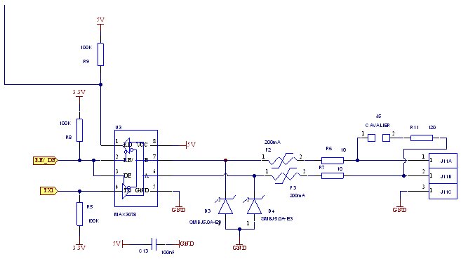
My schematic:

  • Hello Greg,

    The SN65HVD08 has "Receiver Failsafe" biasing to handle invalid bus states caused by Open Bus conditions such as an open connector, or an Idle Bus that occurs when no driver on the bus is actively driving.  This is accomplished by offsetting the input receiver thresholds so that the indeterminate range, where the output could be sampled either as a high or a low, does not include the zero volts differential level.  The device will output a High on the R pin when the differential voltage on the bus is more positive than -10mV, and will output a Low on the R pin when the differential voltage on the bus is more negative than -200mV.  However the voltage range in between -200mV and -10mV is the "indeterminate range" where the device could output either a High or a Low depending upon a number of factors and the exact point of transition will be device specific. 


    If I understand you correctly, in the case you are observing the R output as Low when there is an Open bus, you do not have the 120 ohm termination resistor connected to the bus and there is nothing to set the voltage on the A and B pins or provide a current path between them to drain any voltage potential that may exist on the bus pins from capacitance.  Have you measured the actual differential voltage on the A and B pins during this state when there is no connection and the R pin should be a High?  It could be that there is a negative differential voltage on the bus pins and without a current path between A and B, or a driving condition on the bus to set the differential voltage to a voltage more positive than -10mV, the device could be working properly.  Could you measure the voltages on the A and B pins under the various setup conditions (one board with open connection but no termination resistor, one board with open connection with 120 ohm termination resistor, two boards in High Z mode with no termination resistor, etc.) and note the value of the R pin under those conditions?  This will help determine when the R pin is going to be a High or a Low and what might be needed to do in your application.

    You could also reference the following App Notes for additional information on RS485 Receiver Failsafe Biasing.

    http://www.ti.com/lit/an/slyt324/slyt324.pdf

    http://www.ti.com/lit/an/slyt514/slyt514.pdf

    Regards,

    Jonathan

  • Hello Jonathan,
    I have test, when i dont have open connection, I have -0.196V, pin R have 0V
    when i have 2 driver SN65HVD08 in hight Z mode, I have -230mv, pin R have 0V
    when I have 120 ohm termination resistor i have 0V, pin R have 5V
    I have remove my protection diode, and open connection, I have 0.0096V and pin R have 5V.
    The conclusion is: the driver respect it specification but my protection diode (SMBJ5.0A-E3) is not adapted for the driver.
    In the SN65HVD08 fig23 it propose a TVS diode ref: CDSOT23-SM712, I suppose we dont have my problem with it.
    My diode have 800µA of reverse currant and the CDSOT23-SM712 have 20uA this is certainly the difference for resolve the problem.
    I go to test it.
    Thanks
  • Hello,
    I have test a TVS diode ref: SMP100LC-8, in hight Z mode, I have -9.8mV and pin R have 5V.
    My new diode have 2µA of reverse current.
    The problem is resolved!
    Thanks
  • Hello Greg,


    Thank you for posting your question to us on this forum and providing the details of your tests with the TVS diodes!  I am glad your problem is resolved and hope I was of help to you.  Please feel free to contact us again with any future question.

    Regards,

    Jonathan