This thread has been locked.

If you have a related question, please click the "Ask a related question" button in the top right corner. The newly created question will be automatically linked to this question.

SN65LVDS311 - Using YCbCr instead of RGB signal, CP

Guru 19785 points

Other Parts Discussed in Thread: SN65LVDS311, SN65LVDS314

Hello Team,

I have two questions about SN65LVDS311.

[Q1]
Could you please advise us if one could use SN65LVDS311 as below ?
Customer will use YCbCr input to R (Y) and G (Cb and Cr).
I believe this device is just a Serializer device, so it could be used as long as the receiver device could understand the bit map of the signal lanes.
Unused pins, B[7:0] and DE, will be tied to GND.

[Q2]
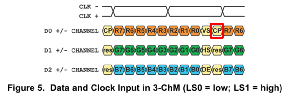
What is "CP" bit ? I couldn't find the explanation of this bit.
Does this bit show the even or odd information of total number of "1" included in the D0, D1, and D2 channel ?
"1" is for even, "0" is for odd ?

Thanks in advance.

Best Regards,

Kawai

  • Hello Kawai,

    You are correct, the SN65LVDS311 only serializes the input signal and the application you proposed is correct as long as the receiver is capable to interpret the incoming information. Regarding the CP bit you are correct too, it is just a polarity bit generated by the SN65LVDS322.

    Regards,
    Diego.
  • Hello Diego-san,

    Thank you for your information.

    I have one question to your comment. I believe SN65LVDS322 is a typo, is it SN65LVDS311 ?

    We were asked about CP bit detail so that customer could confirm if they can use this device to interface their receiver block.
    If CP bit indicates whether the total number of 1s in all lanes is EVEN (CP="1") or ODD (CP="0"), they can use the device.

    Best Regards,
    Kawai

  • Kawai-san,


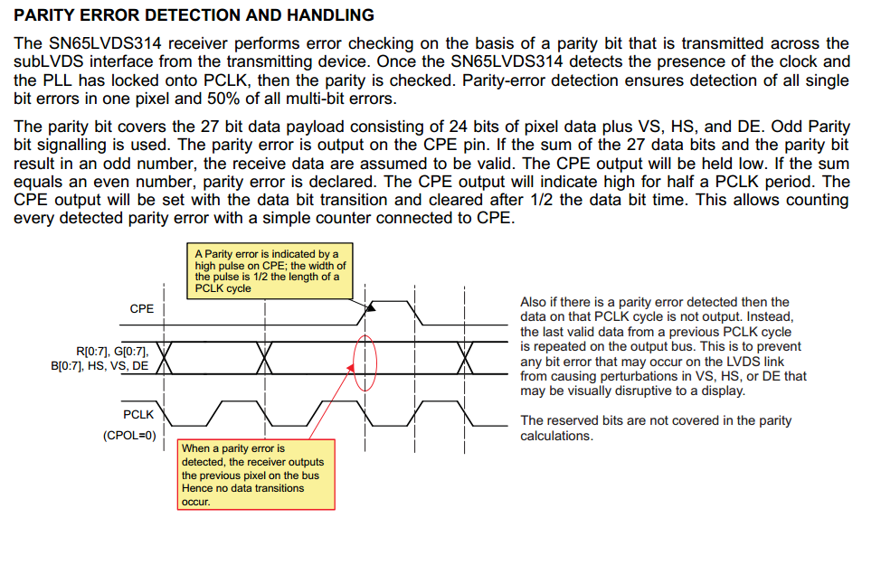
        My bad, the 322 is a typo. And the parity is Odd, please see the parity error detection and handling extracted from the receiver (SN65LVDS314 datasheet, page 10).

    Best regards,

    Diego.

  • Hello Diego-san,

    I believe all the data below is sent from Transmitter (SN65LVDS311) side. I am thinking that receiver detects CP bit in the serial data and then decides whether it has parity error or not, outputs at CPE pin. Am I misunderstanding ?


    Customer question is the mechanism how SN65LVDS311 outputs CP bit in the serial stream.

    Best Regards,
    Kawai

  • Hello Kawai,


        The receiver corresponds to the transceiver, so it is the same. the customer only has to emulate the receiver in terms of CP handling.

    Regards,

    Diego.

  • Hello Diego-san,

    Customer will not use TI receiver. In that case, SN65LVDS311 transmitting CP bit must meet their dedicated receiver specification.

    Their receiver is expecting the SN65LVDS311 transmitting CP (parity) bit to be,
    CP="1" when 1's within the data is even,
    CP="0" when 1's within the data is odd.

    Does SN65LVDS311 meet the above requirement ?
    I believe there can be an opposite case ("1" for odd, "0" for even).
    Which is SN65LVDS311 designed ?

    Best Regards,
    Kawai
  • Hello Kawai,

        I understood that the customer plans to use a different receiver, and as I mentioned the SN65LVDS311 matches with the LVDS314, that's why I included the receiver documentation, where you can see that it handles odd parity, which is the same parity that the customer needs ("1" when 1's within the data is even, and "0" when 1's within the data is odd). Therefore the customer can use our device.


    Regards,

    Diego.

  • Hello Diego-san,

    Sorry that I could not understand good enough. Thank you for the explanation, now I am clear.
    We greatly appreciate for your support.

    Best Regards,
    Kawai