This thread has been locked.

If you have a related question, please click the "Ask a related question" button in the top right corner. The newly created question will be automatically linked to this question.

TMDS181 DDC Connections in a Sink Application

Other Parts Discussed in Thread: TMDS181, PCA9306, TXS0102

Hello,

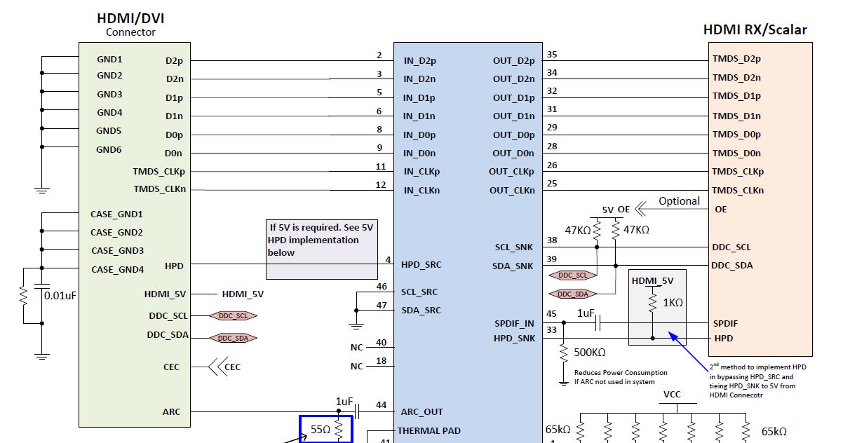
I have an HDMI 2.0 sink application which uses the TMDS181.   The initial implementation leveraged a schematic similar to Figure 35/36 in the datasheet.

There are a few things hanging off the DDC bus.   They are:

- TMDS181

- EEPROM for EDID

- MOSFET based level translators (required for interfacing to the digital end-point)

Unfortunately, the circuit is failing the capacitance requirement for HDMI certification.    I've tried hooking up the circuit like an active cable configuration showing in figure 37 of the datasheet.   This configuration leverages the TMDS181 SCL_SRC/SDA_SRC pins.

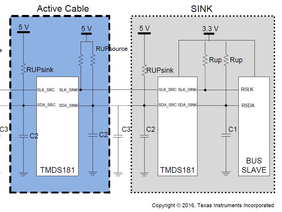
This works, and I suspect it's because the TMDS181 acts like a buffer.   Would you confirm that this is an acceptable use case for a fixed HDMI 2.0 sink application?

Thanks.

Don

  • Hi Donald,

    TMDS181 has an active DDC block which works as a buffer, this block implements clock stretching compliant with I2C specification.
    We have seen some HDMI sources/sinks that don't support clock stretching(although they should) that's why figure 35/36 implement DDC snoop mode.

    Regards
  • Thanks Moises,

    So if my HDMI end-point supports clock stretching, then using the TMDS181 in an active buffer configuration is OK.

    Don
  • Hi Donald,

    This is a sink application, you still need the video source to support clock stretching.

    Regards
  • Hi Donald,

    Excellent question. The data sheet has very little coverage for the functionality of the internal DDC block in TMDS181. There are some mysterious features like "clock stretching" which are mentioned but not discussed. Because of this, the only safe way for a customer seems to don't use the DDC block at all and use an external DDC buffer part instead. This is not a cost-efficient solution and a couple of times early I'd attempted to ask TI to provide more information for the DDC block. Unfortunately, they actually refused. You're from TI so the hope is this time they will pay more attention to the matter.
  • Ah! Got it.

    Two questions:

    1. If my application needs to support all possible video sources, than I have to use DDC snoop mode. Correct?
    2. With regard to HDMI sources that don't support clock-stretching; could these sources be accuractly categorized as not HDMI compatible (and thus won't pass certification)?

    Don
  • Hey Igor,

    Thanks for responding. I looked through your previous posts and found one rather insightful thread on the subject. It helped my understanding of the subject. Thank you for posting it.

    Don
  • Hi Donald, Igor,

    1) yes using snoop mode will increase interoperability

    2) Here is a void because HDMI specification requires to follow I2C specification, but clock stretching is not tested on HDMI compliance testing.

    I'm sorry if my previous answers haven't been so clear, DDC block just implements clock stretching , I'm attaching a capture from DP159.

    Purple signal is has a higher frequency, so DP159 has to stretch it, make it slower, then it generates another clock with slower frequency.

    If there is a level shifter in DDC, it may work as a DDC buffer too.

  • Thanks Moises,

    So if I want to maintain maximum interoperability with all HDMI sources, and I want to pass HDMI compliance (given my configuration), I'll need to operate the TMDS181 in snoop mode, and add an I2C buffer between the HDMI connector and the rest of my components on the DDC bus.

    If true, do you have any part recommendations?

    Also, I've noticed that many of the translator/buffer parts require translating to a lower voltage (typically 3.3V). Would it be possible to setup my system like so:

    HDMI Connector -> TMDS181 (snoop mode, hanging off bus) -> Level translator -> EDID (EEPROM) + HDMI endpoint

    I propose this because EEPROMs and HDMI endpoints can and do typically operate at lower I2C voltages, while the TMDS181 seems to require 5V levels on the DDC bus (again in snoop mode). I'm looking at the PCA9306 as a potential fit for this (low cost, small package).

    Don
  • Hi All,

    Donald, I'm glad to hear this. My pleasure.

    Moises, I've done some research early and to the best of my knowledge the CTS has HF1-23 test that reads "Source E-DDC Protocol - Clock stretching". Anyway there is the summary https://www.dropbox.com/s/omot0vhw7ix6bbb/HDMI-SCDC_Tref.pdf?dl=0

    The scope screen shows that the DDC block implements a byte-level clock stretching, not a bit-level one ("clock stretching" hears as an urban dictionary word when no context is specified). What about the timing parameters for that stretching? For how long time TMDS181 ties the SCL line low doing the stretching?

  • Hi Donal, Igor,

    Thanks for sharing the document, you are right on HDMI2.0 there is a test for clock stretching, but there is no test in HDMI1.4
    So, the device may work fine with HDMI2.0 video source but it may have problems with HDMI1.4 sources.
    I need to look for the amount of stretching that is added.

    Is common that HDMI transmitters/receivers are 5V tolerant on DDC and HPD, is more common to see level shifter in DP++/HDMI applications.
    PCA9306 looks like a good match, I have seen TXS0102 too, you can contact those groups for better support.

    Regards