This thread has been locked.

If you have a related question, please click the "Ask a related question" button in the top right corner. The newly created question will be automatically linked to this question.

SN75DP130 used for HBR2 Sink Application Issue

Other Parts Discussed in Thread: SN75DP130, SN65DP141, TUSB546-DCI

Hi,
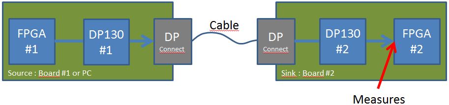
I'm using the SN75DP130 in order to equalize the displayport signal in a sink application
The SN75DP130 is connected to a FPGA
In summary : DP Connector -> SN75DP130 -> FPGA

I have some difficulty to obtain a locked video signal in HBR2 (4K60) through a 10m cable.
Notes :
- I use a Lindy Gold cables
- That's work over 10m cables with monitors sink
- That's work over 5m cables with my product (i'll will try on 7.5m soon)

Regarding the SN75DP130 :
Based on the TI Application Report : slla349.pdf (Implementation Guide: DP130 in a Sink) :
The SN75DP130 is actually programmed with EQ_I2C_Enable (reg 05.7) to High (Enabled), Link_Training_On/Off (reg 04.2) to Low (Off)
I also set the AEQ(L1) to 6dB(HBR)/13dB(HBR2) and i have disabled the Squelch (It's seem to be better than 40mV or 80mV)
Also, i write on DPCD : HBR2, 4lanes, Power mode Normal

I already try all AEQ(L1) parameters from 0dB to +18dB(HBR2) without success.

Regarding the schematics :
Based on TI eval board (sllu143a.pdf) and others DP eval board, i have connected AC-coupling (100nF) on each differential pair between the connector and the SN75DP130.
But on the VESA DisplayPort Standard Version 1.4 (§3.5.2 Main-Link Electrical Sub-Block ; Figure 3-34), there are 2 topology :
- A : the connector is directly connected to the downstream device
- B : there are AC-Coupling and also 100k to 1M pull down resistor before the capa in order to fix the common voltage.

Here my questions :
- Is somebody use the SN75DP130 as sink application over long cable without problem?
- Is the SN75DP130 is really the good product for HBR2 Sink application?
- Is the SN75DP130 need AC-Coupling or it's recommended to use the VESA topologies?
- In a future revision of the board, i want to add ESD protection with diodes such as Murata LXES15AAA1-100. Is it a bad idea vs integrity of signal?

Best regards,
Olivier

  • Hello,
    We are reviewing your questions and we'll reply soon.
    Regards
  • Hi Rollin,

    -Since the cable losses don't depend only on cable length, we don't have information about the cable lengths, we just provide the available EQ.
    -We have passed DP compliance in sink applications, but it doesn't tests cable length it just test the sink devices can receive signal with certain characteristics.
    -DP130 is intended for DP1.2, in that spec only topology A is available, topology B should be to maintain common mode voltage low.
    -ESD diodes have some effect on SI, but is better to be protected.

    Could you share eye diagrams of input and output signals?

    Regards
  • Hi Moises,

    Thanks for your answers and sorry regarding my delay to reply.

    See attached some eye diagrams on the FPGA sink side (DisplayPort.rar file).

    The source is an FPGA with an SN75DP130 driver. The cables used are 3 and 7 meters lenght and 2 quality of cable for 7 meters.

    There is an SN75DP130 used as EQ before the FPGA Sink.

    Note that the 7mBlack cable works only if i disable the squelch feature.

    I have plan to optimize CTLE of the FPGA receivers on next week.

    Regards,

    OlivierDisplayPort.rar

  • Hi Rollin,
    Thanks for sharing the eye diagram, are these for DP130 input or output?
    Could you share the eye diagrams on the other side of DP130?
    Regards
  • Hi Moises,

    The probes are fixed at the sink FPGA. See the diagram bellow :

    Also, you can see attached the DP schematic parts.

    Regards, Olivier

  • Hi Rollin,

    This is a public forum, I have downloaded and removed your schematic from the previous post.
    I have reviewed the schematic since it works you may leave it as is, but I have a couple comments:
    The AC capacitors close to J2 connector are not needed because there are AC caps in DP130 #1
    DP130 #2 is not following the application note for sink applications.

    DP130 monitors AUX channel to configure itself, having two DP130 in cascade will give some problems with this link training.
    Please configure both DP130 by I2C, disabling link training to get better results.
    You can set the highest Vod with the highest supported PE in DP130 #1
    Disable Squelch on DP130 #2
    Select the right EQ on DP130 #2.

    Regards
  • Hi Moises,

    Ok for the caps, I already replaced them by 0Ohm resistor.

    Note that the DP source can be either FPGA#1+DP130#1 or another source like computer. And also the couple FPGA#1+DP130#1 can be used with displays.

    So i prefer to keep DP130#1 with link Training enabled, that's works well like that with all displays and all cables i have.

    Regarding the Sink (DP130#2), when i disabled the squelch, the link training works well over 7 or 10m of cable, the FPGA is clock recovered and symbol locked but the video status of the DP IP is unlocked, that's mean there some errors. The EQ on DP130#2 need to be adjusted for this specific case (actually the setting is 6dB/13dB). I note also that to much AC_Gain is not good for shorter cable.

    I have received the SN65DP141 eval board. Do you think is a better chip for this application?

    Regards,

    Olivier

  • Hi Rollin,

    Is good to know the applications is working with some adjustments.
    DP130 was not intended for sink applications, so the application note was released to configure it by I2C interface.
    As you have noted, when setting a high EQ to work with long cables may produce problems with short cables because of over-equalization.
    So, here would be a trade-off, DP141 has fixed EQ too, so, although it has more EQ capabilities the issues will be the same.
    For DP1.4 we recommend to use TUSB546-DCI following the application note, although it has link training too.
    Another option is to use DP159 in x-mode, this device has automatic EQ. In automatic EQ it has two ranges, low range for source application and high range for sink application, by default it works in source mode, you have to configure it by I2C to work in sink mode.

    Regards