This thread has been locked.

If you have a related question, please click the "Ask a related question" button in the top right corner. The newly created question will be automatically linked to this question.

DS100DF410 support for 1GbE

Other Parts Discussed in Thread: DS100DF410, DS110DF410, DS125DF410

Hi,

We have problems to operate 1GbE retimer, because probably the simple setting, according to the DS, is not working or is missing some configuration.

DS 7.3.12
write reg 0x09 (bit 5) = 1
write reg 0x1E (bit7:5) = "000"

The 1GbE external testset is not receiving any data from retimer.

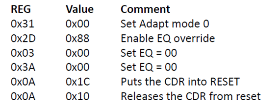
I already applied the configs (commands below) of the "DF410 Support for 2.5G Ethernet" discussion, but is not working:
Reg 0xFF = 0x0C //Access channel registers
Reg 0x2F[7:4] = 1100'b // Set lock rate for Interlaaken-2 (10.3125 Gbps with Divide-by-1 VCO divider only)
Reg 0x1E[7:5] = 000'b // Output raw data if CDR is not locked
Reg 0x3F[7] = 1'b //This is a reserved bit that must be set to ensure appropriate raw data is output


Thanks,
Érico Sawabe

  • Hello Érico,

    It sounds like your retimer is not properly locking to the signal. The default settings of the DS100DF410 mute the output when not locked to a signal. Could you confirm a few things about your setup so I can best assist you?

    1. Which retimer are you using (DS100DF410, DS110DF410, DS125DF410)?
    2. Which data rate(s) are you having trouble getting the device to lock? Are we interested in 2.5GbE, 1GbE, or both?

    Regards,

    Dan

  • Hi Dan,

    1. We are using the DS100DF410
    2. We just having problems with 1GbE mode. But the 10GbE is working fine.

    Could you help me with the right register configuration to be set for 1GbE, and status to check what is happening with retimer behaviour?

    Regards,
    Érico Sawabe

  • Hi Érico,

    In my previous experience, the DS100DF410 will lock to 1GbE with the default registers settings. My recommendation would be to power up the DS100DF410 with the default register settings and monitor register 0x02 for lock.

    It might be helpful for me understand your test setup and the registers that have been programmed to something other than the default values so I can try to replicate your issue on my side.

    Regards,

    Dan

  • Hi Dan,

    My setup is this 1GbE test is:

    Testset 1GbE <=> SFP(1.25G) <=> Retimer <=> FPGA (internal loop)

    Obs.: The datapath is working for 10GbE without errors.


    The items bellow are the verifications about the retimer tests to help your analysis:

    Test 1:
    - Monitoring the register 0x02 after the retimer power up (without register changes) and the testset sending 1GbE traffic, the CDR status is lock. But there are no signal of frame, sync and valid data for testset.

    ------------------------------
    CDR Status, channel 0:
    ------------------------------
      PPM_Count_met            = 0
      Auto_Adapt_Complete  = 0
      Fail_Lock_Check           = 1
      Lock                                  = 1
      CDR_Lock                       = 1
      Single_Bit_Limit_Reached  = 0
      Comp_LPF_High           = 1
      Comp_LPF_Low            = 1
    ------------------------------

    Verification 1:
    Next step, according to the DS100DF410, for 1GbE mode operation is needed to set:
    REG 0x09 bit[5] = 1'b           //Enable bit to override sel_retimed_loopthru and sel_raw_loopthru with values in reg 0x1E[7:5]
    REG 0x1E bit[7:5] = 000'b  //raw data

    And the reg 0x02 still has the same status above, and the testset also (without receiving valid data).

    Verification 2:
    After that, I tried to set some configurations found at "DF410 Support for 2.5G Ethernet" forum discussion, as follow:

    REG 0x2F bit[7:4] = 1100'b  // Set lock rate for Interlaaken-2 (10.3125 Gbps with Divide-by-1 VCO divider only)
    REG 0x3F bit[7] = 1'b            //This is a reserved bit that must be set to ensure appropriate raw data is output

    But again, there is no valid data on testset and the status (0x02) changed to:
    ------------------------------
    CDR Status, channel 0:
    ------------------------------
      PPM_Count_met             = 1
      Auto_Adapt_Complete   = 0
      Fail_Lock_Check            = 0
      Lock                                   = 0
      CDR_Lock                        = 0
      Single_Bit_Limit_Reached  = 0
      Comp_LPF_High             = 0
      Comp_LPF_Low              = 0
    ------------------------------

    So, apparently, the default settings of this retimer power up or even configure for 1GbE registers didn´t work.


    Test 2:
    - In this test, we have some necessary retimer initialization settings in our project, as follow:

    REG 0x31 bit[6:5] = 11´b            //adaptation/lock mode: 11: adapt CTLE until lock, then DFE, then EQ until optimal
    REG 0x2F bit[0] = 1'b => 0'b      //starts CTLE adaption (self-clearing): writes 1'b and writes 0'b after
    REG 0x24 bit[2] = 1'b                  //1: Manually start DFE adaption, self-clearing.
    REG 0x2D bit[2:0] = 1'b              //Controls the VOD levels of the high speed drivers: 0.7 SELECTED VOD (V, PEAK-TOPEAK, DIFFERENTIAL)
    REG 0x15 bit[6] = 1'b                  //Driver De-emphasis Range
    REG 0x15 bits[2:0] = 110'b       //Driver De-emphasis Setting[2:0]: -4.5 DE-EMPHASIS SETTING (dB)

    Obs.: this initialization is working fine for 10GbE traffic with eye diagram measured.

    After retimer initialization, the lock status (0x02) for 1GbE setup is:
    ------------------------------
    CDR Status, channel 0:
    ------------------------------
      PPM_Count_met             = 1/0
      Auto_Adapt_Complete   = 0
      Fail_Lock_Check             = 0
      Lock                                    = 0
      CDR_Lock                        = 0
      Single_Bit_Limit_Reached  = 0
      Comp_LPF_High             = 0
      Comp_LPF_Low              = 0
    ------------------------------

    And the testset without receiving valid data. There are no signal of frame and sync also.

    Then, I repeated the registers configuration of Verification 1 and Verification 2, and suddenly the testset recognized frame, sync signals without any errors alarm on the testset. But, it not always works if I changed some of those parameters to 10gbE mode, for example.
    And checking the lock status, we still have lock = 0, but the testset is receiving valid data with no errors.
    ------------------------------
    CDR Status, channel 0:
    ------------------------------
      PPM_Count_met             = 0
      Auto_Adapt_Complete   = 0
      Fail_Lock_Check            = 0
      Lock                                   = 0
      CDR_Lock                        = 0
      Single_Bit_Limit_Reached  = 0
      Comp_LPF_High             = 0
      Comp_LPF_Low              = 0
    ------------------------------

    Does it make any sense?

    So, it is hard to discover until now, what is going on for sometimes the 1GbE data traffic works and sometimes not.
    The datasheet doesn´t describe in details the registers 0x2F bit[7:4] and 0x3F bit[7] (reserved bit), that were our tries after seen "DF410 Support for 2.5G Ethernet" forum discussion.

    Hope it helps for your futher analysis.

    Regards,
    Érico Sawabe.

  • Hi Érico,

    Thanks for typing up your test setup. This will really help me get to the bottom of this. I'm going to need some time try some things in our lab and make recommendations. I'll update you by the close of business tomorrow. If you figure anything out on your side in the meantime do let me know.

    Just to make sure I have this right, Verification 1 and Verification 2 only work after changing to register settings to the settings of Test 2 - but in Test 2 you do not see lock for 1GbE. Am I interpretting this correctly?

    Thanks again,

    Dan

  • Hi Érico,

    My suggestion would be to try the following and see if either of these helps:

    1. Disable SBT check  -- Reg 0x0C[3]  = 0'b
    2. Set to ref_mode=0  -- Reg 0x36[5:4] = 00'b

    Regards,

    Dan

  • Hi Dan,

    I tried to apply those configuration, but still not working properly.

    Is there any condition of these settings like wait some status or sequence commands to apply?

    Sometimes when it works, according to the combination explained in the last post, I do the channel register reset (default values) before to apply those commands:
    Reg 0x00[2] = 1'b wait 100us Reg 0x00[2] = 0'b

    Regards,
    Érico Sawabe

  • Hi Érico,

    There isn't a particular sequence that is needed for the register settings we have discussed so far.

    Could you try using adapt mode 0 and forcing zero boost with the rest of the settings default while monitoring 0x02?

    Instructions below:

    Thanks,

    Dan

  • Hi Dan,

    I applied those configurations as you suggested, and monitor the CDR status as follow:

    ------------------------------
    CDR Status, channel 0:
    ------------------------------
      PPM_Count_met            = 0
      Auto_Adapt_Complete  = 0
      Fail_Lock_Check           = 0
      Lock                                  = 0
      CDR_Lock                       = 0
      Single_Bit_Limit_Reached  = 0
      Comp_LPF_High             = 0
      Comp_LPF_Low              = 0
    ------------------------------

    ------------------------------
    CDR Status, channel 0:
    ------------------------------
      PPM_Count_met             = 0
      Auto_Adapt_Complete   = 0
      Fail_Lock_Check             = 1
      Lock                                    = 0
      CDR_Lock                        = 0
      Single_Bit_Limit_Reached  = 0
      Comp_LPF_High             = 0
      Comp_LPF_Low              = 1
    ------------------------------

    ------------------------------
    CDR Status, channel 0:
    ------------------------------
      PPM_Count_met             = 0
      Auto_Adapt_Complete   = 0
      Fail_Lock_Check             = 1
      Lock                                    = 1
      CDR_Lock                        = 1
      Single_Bit_Limit_Reached  = 0
      Comp_LPF_High             = 1
      Comp_LPF_Low              = 1
    ------------------------------

    ------------------------------
    CDR Status, channel 0:
    ------------------------------
      PPM_Count_met            = 0
      Auto_Adapt_Complete  = 0
      Fail_Lock_Check           = 0
      Lock                                  = 0
      CDR_Lock                       = 0
      Single_Bit_Limit_Reached  = 0
      Comp_LPF_High             = 0
      Comp_LPF_Low              = 0
    ------------------------------

    The CDR status is intermittent.
    Any opinion of this behaviour?


    - Missing question: Sorry I didn´t see this follow up

    DAN: Just to make sure I have this right, Verification 1 and Verification 2 only work after changing to register settings to the settings of Test 2 - but in Test 2 you do not see lock for 1GbE. Am I interpretting this correctly?

    That´s correct. Those settings in Test 2 works, but not always (thats the point), even the CDR is not locked.

    Regards,
    Èrico Sawabe


  • Hi Èrico,

    Thanks for sending me those statuses and for clarifying my understanding of the issue. Could you also provide the values you are observing on registers 0x03, 0x27, and 0x28 when the CDR is locked?

    Regards,

    Dan

  • Hi Dan,

    Here are the other status of the same situation described in my last post:

    CDR Status, channel 0:
    ------------------------------
      PPM_Count_met             = 0
      Auto_Adapt_Complete   = 0
      Fail_Lock_Check           = 1
      Lock                                 = 1
      CDR_Lock                      = 1
      Single_Bit_Limit_Reached  = 0
      Comp_LPF_High             = 1
      Comp_LPF_Low              = 1
    ------------------------------
    > "eq_bst0"
    0
    > "eq_bst1"
    0
    > "eq_bst2"
    0
    > "eq_bst3"
    0
    > "heo_veo"
    ------------------------------
      heo                  = 59
      veo                  = 168
    ------------------------------

    The HEO and VEO (0x27 and 0x28) values are changing. This variation sometimes at reading is HEO= 0 or HEO= 59, VEO= 0 and VEO= 168. But, it gets most of time in HEO= 59 and VEO= 168.


    Regards,
    Érico Sawabe

  • Hi Érico,

    The HEO and VEO values you are observing look great when it is working. Could you confirm for me that you are seeing this intermitten CDR lock after performing the procedure we discussed?

    Thanks,

    Dan

  • Hi Dan,

    Yes, this intermitten CDR lock happens when I follow this procedure.


    I dumped some registers, when the data flow is coming back correctly to the testset:

    > "rate1"
    0
    > "rate0"
    0
    > "subrate1"
    0
    > "subrate0"
    0
    > "bypass_pfd_ov"
    0
    > "pfd_sel_data_mux"
    0
    > "res_0x3f_bit7"
    1
    > "en_pd_cp_ov"
    0
    > "cp_en_cp_pd"
    1
    > "cp_en_cp_fd"
    1
    > "pdiq_sel_div"
    4
    > "set_cp_lvl_lpf_ov"
    0
    > "lpf_dac_val"
    21
    > "single_bit_limit_check_on"
    1
    > "ref_mode"
    3
    >
    ------------------------------
    CDR Status, channel 0:
    ------------------------------
      PPM_Count_met             = 0
      Auto_Adapt_Complete  = 0
      Fail_Lock_Check           = 0
      Lock                                  = 0
      CDR_Lock                      = 0
      Single_Bit_Limit_Reached  = 0
      Comp_LPF_High             = 0
      Comp_LPF_Low              = 0
    ------------------------------
    >
    > "adapt_mode"
    0
    > "eq_bst_ov"
    1
    > "res_0x2d_bit7"
    1
    > "eq_bst_ov"
    1
    > "eq_bst0"
    0
    > "eq_bst1"
    0
    > "eq_bst2"
    0
    > "eq_bst3"
    0
    > "fixed_eq_bst0"
    0
    > "fixed_eq_bst1"
    0
    > "fixed_eq_bst2"
    0
    > "fixed_eq_bst3"
    0
    > "en150_lpf_ov"
    1
    > "eq_limit_en"
    1
    >
    ------------------------------
    CDR Status, channel 0:
    ------------------------------
      PPM_Count_met             = 0
      Auto_Adapt_Complete  = 0
      Fail_Lock_Check           = 0
      Lock                                   = 0
      CDR_Lock                      = 0
      Single_Bit_Limit_Reached  = 0
      Comp_LPF_High             = 0
      Comp_LPF_Low              = 0
    ------------------------------
    > "eq_bst0"
    0
    > "eq_bst1"
    0
    > "eq_bst2"
    0
    > "eq_bst3"
    0
    >
    ------------------------------
      heo                  = 0
      veo                  = 0
    ------------------------------


    Regards,
    Érico Sawabe

  • Hi Érico,
    I've sent you a friend request so we can privately message to exchange some contact information so we can work to find a solution to this issue. Please respond at your earliest convenience.
    Regards,
    Dan
  • Hello Dan,

    Sorry about the late response, but I was envolved in other designs.

    I return the tests and read again the whole Datasheet and your previous comments we restart the tests from the beggining and the traffic in GBE ports are working now. Can you just clarify our understanding with the below questions ?

    - when DS100DF410 is running in Ref_mode 3 Mode (External 25Mhz clock) the VCO locks either at 10GBE or 1GBE without any register intervention or additional configuration ?

    - when DS100DF410 is running in Ref_mode 0 Mode (Reference Clock Not Required) the VCO locks only in 10GBE data rates, for lock to 1GBE it is necessary to set CDR to the bypass mode ?

    Thanks

  • Hi Erico,

    Your two statements above are correct.

    Regards,

    Lee