This thread has been locked.

If you have a related question, please click the "Ask a related question" button in the top right corner. The newly created question will be automatically linked to this question.

Questions regarding TUSB320LAI/TUSB320HAI

Other Parts Discussed in Thread: TUSB320LAI, TUSB320HAI, TUSB320

Hi Sir,

I have some questions regarding TUSB320LAI/TUSB320HAI when I do the evaluation. Can you please kindly help to answer? Thanks a lot in advanced.

Questions regarding TUSB320LAI/TUSB320HAI:

  1.  In the datasheet page 3,  it is stated in Pin Function stable that both EN_N (TUSB320L) and EN(TUSB320H) must be held low at least for 50 ms after VDD has reached its valid voltage level. Should it be “EN must be held LOW at least for 50 ms after VDD has reached its valid voltage level. EN_N must be held HIGH at least for 50 ms after VDD has reached its valid voltage level.”?
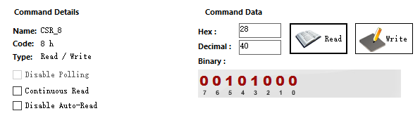
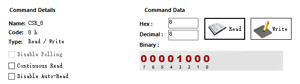
  2.  In datasheet page 17, what is the value will be in the Register 0x08[5:4] if the device is configured at UFP mode and operates at unattached state? In table 3 (page 12), there is an option for OUT1/OUT2 outputs "Default Current in Unattached State". I cannot find the similar option in Register 0x08[5:4].
  3.  In datasheet page 17, what is the relationship between Register 0x08[3:1]= 100 (audio accessory) and Register 0x08[3:1]= 101(audio charged thru accessory)? My understanding is 100 = passive audio accessory. And audio accessory = passive audio accessory + audio charged thru accessory, is that right? However, according my test, when 0x08[5:4]= 10, 0x08[3:1] is 100, not 101?
  4.  In the datasheet page 19 & 20, what is the difference between 0x0A[0] & 0x45[2]? My understanding is, if this bit is set, the CC1 & CC2 are configured to high impedance state (disable Rp & Rd). can you please confirm?
  5.  In the datasheet page 19, what are the applications for DISABLE_UFP_ACCESSORY bit?
  6.  In the datasheet page 18, a read and write 1 to 0x09[4] bit to clear the interrupt bit, or simply a write 1 to 0x09[4] to clear the interrupt bit?

  • Hello user,


        Here is my feedback:

    1. Your assumption is correct.
    2. THe value is 00, the GPIO mode reports OUT1/OUT2 as off when unattached due to its limitations, the I2C mode is able to report the precise attached/unattached state by means of the register 0x09, so there is no need for differentiation between unattached & default detected current in I2C mode.
    3. The difference is the precense of VBUS. VBUS should be provided before or at leaset at the same time the Ra pins, in this case you should be able to read 0x08=2A.
    4. The control bit 0x45[2] is intended for VCONN testing, meanwhile the bit 0x0A[0] is for practical disconnection. If you want to dissable the termination for disconnection purposes I recommend to use the bit 0x0A[0].
    5. In order to disable the detection of accessories in UFP mode (the CC pins won't toggle when this bit is ON)
    6. Simply write a 1 will clear the interrupt.

    Regards,

    Diego.

  • Dear Diego,

    Thanks a lot for your prompt responses. Most of the questions are answered.  However, I still have questions on item 3, 4 and 5.

    3. The difference is the precense of VBUS. VBUS should be provided before or at leaset at the same time the Ra pins, in this case you should be able to read 0x08=2A.

    James: In my test, I short CC1 and CC1. Then I connects a small board with a 1kΩ Ra on the CC pin, by a type-C cable. If VBUS is provided before or at lease at the same time the Ra pins, the reading of Register 0x08 is always 28 (see first figure). If VBUS is provided after the Ra pins, the reading of Register 0x08 is always 08 (see second figure).  I cannot find 0x08=2A. it is possibly a bug? Can you please check it?

    4. The control bit 0x45[2] is intended for VCONN testing, meanwhile the bit 0x0A[0] is for practical disconnection. If you want to dissable the termination for disconnection purposes I recommend to use the bit 0x0A[0].

    James: do you mean the TUSB320 also support VCONN power to provide power for electronically marked cable? I cannot see any information about VCONN function. Can you please provide some information? Moreover, when I set Register 0x45[2], the CC1 and CC2 pins are pulled down to GND. Neither is pulled up to VDD as what is definited by VCONN.

    5. In order to disable the detection of accessories in UFP mode (the CC pins won't toggle when this bit is ON)

    James: Can you please clarify the meaning of "toggle"? Do you mean the TUSB320 in UFP mode cannot identify a debug accessory or an audio accessory if this bit is ON? However, I cannot find the TUSB320 can enter debugacc.snk state even if this bit is not OFF.

  • Hello  James,

    Thanks a lot for your quick feedback. Here are my answers, I hope to clarify your doubts and perhaps fix the issue in point 3.

    3.- Your result seems to be abnormal, please try by using two 1K pull downs connected together to GND and share your results (right now I don't have TUSB320HA/LA units to run the test using only one pull-don resistor as your setup, I will try to reproduce your issue early next week).


    4.- The TUSB320LA/TUSB320HA does not support VCONN, the configuration in register 0x45 is intended to avoid any damage on our device when you have VCONN power coming from the cable (which is not allowed by the spec since the VCONN should be directed to the circuitry on the cable itself and the TUSB320 does not provide any Ra on the CC pins).

    5.- In UFP mode the CC pins are toggling in unattached state when the accessory support is active, like in DRP device, but the TUSB320LA/HA is only looking for accessories and not another UFP device. If you disable this feature you will see a constant pull-down Rd's on both CC pins.

    Best regards,

    Diego.

  • Dear Diego,

    Thanks a lot for your quick answers. It helps a lot for my evaluation. I really appreciate. I have additional questions. Please help to answer. Thanks a lot.

    1. I have question on the EN_N.  In the datasheet page 3,  it is stated in Pin Function stable that both EN_N (TUSB320L) and EN(TUSB320H) must be held low at least for 50 ms after VDD has reached its valid voltage level. Should it be “EN must be held LOW at least for 50 ms after VDD has reached its valid voltage level. EN_N must be held HIGH at least for 50 ms after VDD has reached its valid voltage level.”? You said my assumption is right.

    However, I check the figure in datasheet page 21. The EN_N is always pulled down to ground.  Can you please verify which way is correct?

     3- Your comments on the audio charged thru accessory: Your result seems to be abnormal, please try by using two 1K pull downs connected together to GND and share your results (right now I don't have TUSB320HA/LA units to run the test using only one pull-don resistor as your setup, I will try to reproduce your issue early next week).

    James: Today I used two 1K pull downs connected together to GND and there is no change on the test results. The Register 0x08 = 0x28, rather than 0x2A. Can you please share your test result?