This thread has been locked.

If you have a related question, please click the "Ask a related question" button in the top right corner. The newly created question will be automatically linked to this question.

SN75LVDS83B turns off and pulls down SHTDN to 0.8V after a couple hours of operation

Other Parts Discussed in Thread: SN75LVDS83B, TFP401A

Hi Guys,


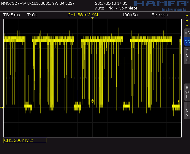
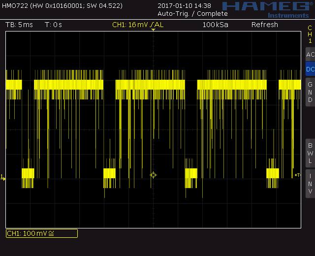
Have anyone experienced any issue when creating circuits with SN75LVDS83B that it shuts down randomly after a few ours of perfect operation? It must not be a heat problem. We get perfect image quality all the time, but sometimes it suddenly pulls down the SHTDN input. We se some random noise on this input and if you connect it directly to VCC without the 4k7 resistor it gives image again. We used the recommended application from the desings from TI.

We measured the input and the data is okay there. The processor which drives it is a 100% functional.


Do you have any recommendation? Any help would be appretiated since we started to run out of idea!


Thanks,

Zoltan

  • Hello,
    We've never heard of an issue like this before. Is the SHTDN going low the only issue you see?
    Does the issue happens if you connect SHTDN to VCC?
    Can you provide a scope capture of the noise you see on SHTDN and of the voltage rails? Is this noise always present?
    Can you share your schematic?
    What is the failure rate?
    Can you swap a failing chip to a passing board and see if the failure follows the part?
    Can you provide the Lot code printed on top of the device?
    Regards
  • Hello,


    Yes, the major issue what we see is that the SHTDN is going low. This causes the screen randomly turns black momentarily and comes back to the image. But after a while it only stays black.

    If we directly connect this pin to VCC that helps the situation a bit. When we did this the the screen turned black only a couple times for a very short time, but after an hour of operation we were not able to get any image out of the IC. There was no output signal on the LVDS pins after that. We had to replace the IC.

    I can provide the scope capture later this day. The nature of the noise is not an oscillation, it is a random pattern. We proved that when the noise is present we see that the screen turns black in sync with the noise.

    We can share the schematics. Shall I upload it here or should I directly send to you? We created the schematics based on the Texas Instruments' recommended application. Since we use this IC with a TFP401A we used filter inductors on power lines also for the LVDS driver.

    We experinced with 5 chips the same issue. We could not swap a chip to a passing board without damaging it unfortunately.

    The LOT code is 44C11K.

    In addition information I can tell you, In the current test scenario we removed filter inductors what we used (CB03YTYH601) and we bypassed them with wires. Now it looks like stable for the last 3 hours.

    Best Regards,

    Zoltan

  • Hello,
    You can send the schematics and scope captures to swat@list.ti.com
    Regards
  • Hello,

    My email was rejected from the swat@list.ti.com with the reason I am not registered on the list.

    what shall I do?

    Regards
  • please email to Gerardo.leyva@ti.com
  • Hi,


    Did you happen to receive my email? I sent it on the 17th of December. I can resend it if necessary.

    Best Regards,

    Zoltan Szabó

  • Hi,
    Sorry for the delay, we are still working on it.

    Regards,
    Gerardo
  • Hi,

    Any update?

    In the mean time we bought some new ICs from a different supplier. We built some new boards. Some of them lasted for over 20 hours before the issue kicked in.

    We also saw some weird coloring on the screen, likeit went to a yellowish shade. In these cases we measured the voltage levels on the HDMI receiver IC blue pixel output pins. (please see attached captures. I also attach one when the colors are alright. ) It was significantly lower than it should have been. Around 0.4~1.1V. Then it came back after a little while to the normal colors. It looks like the inputs on these pins can also pull down the output pins from the out IC. Which results in incorrect voltages. During these circumstances the power lines are clean and at 3.3V.

    The PCBs have been electrically tested before assembly and also the soldering under microscope.

    Thanks,

    Zoltan

  • Hello Zoltan,

    The schematic you've sent looks good for me. I will continue looking at the additional material.

    Regards,

    Gerardo