Part Number: DS110DF111
Other Parts Discussed in Thread: DS110DF410, DS100MB203, DS125DF1610
Hi,
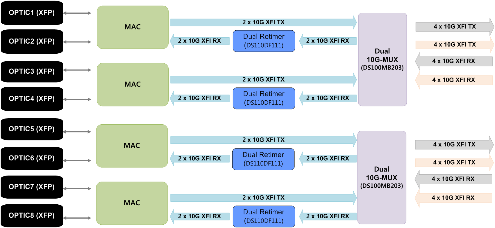
I'm planning to use 4 pieces of DS110DF111SQE/NOPB in one board, as below.
Is it possible for me to connect DS110DF111SQE/NOPB's reference clock as a daisy chain?