This thread has been locked.

If you have a related question, please click the "Ask a related question" button in the top right corner. The newly created question will be automatically linked to this question.

DS92LV18: Deserializer loses PLL lock when sending first data after synchronization

Part Number: DS92LV18

Hello

I am investigating an issue with the DS90LV18 Serializer/Deserializer chipset.

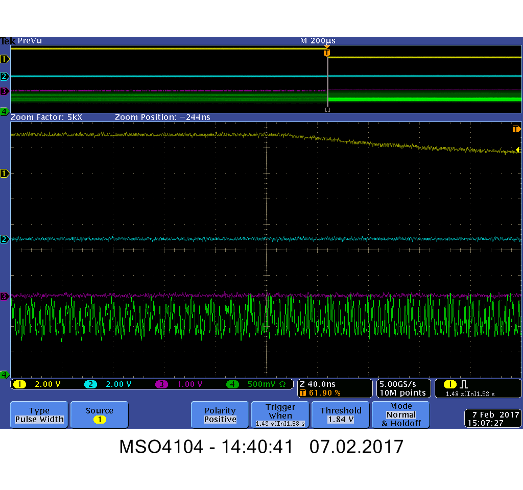
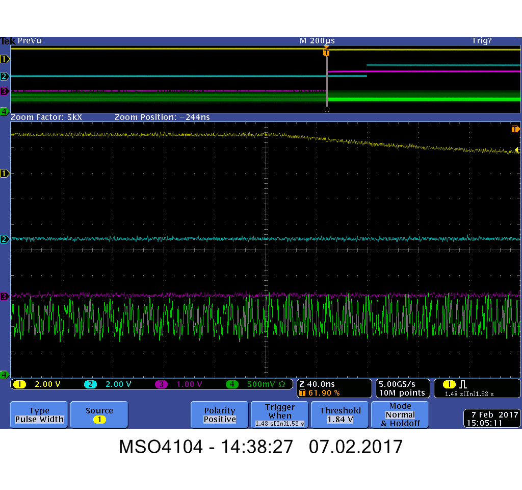
In order to establish the link between Serializer and Deserializer I assert the Serializer SYNC input (pin 20) for about 50ms. As you can see in the attached scope image the PLL of the Deserializer locks (channel #3 goes low). Most of the time the data transfer now works properly (good case). But, about every 40th time the PLL loses the lock (channel #3 goes high) when the very first data packet is sent (spike of channel #1).

After about 15ms the PLL locks again and it seems the link works from now on. I do not understand why the PLL unlocks sometimes. It seems to me that although the PLL lock signal goes low the PLL is not properly locked (e.g. locked to the wrong edge?) and when receiving the first data packet the PLL "realizes" that something is wrong and loses lock.

My questions:

1. What could be the root cause that the PLL unlocks for a short time?

2. Has anyone seen this behavior too?

3. As mentioned, I assert the SYNC input for ~50ms. According to the datasheet this should be by far long enough for the PLL to lock. However, do I have to send the SYNPAT for a longer time?

4. Is there a better way for establishing the link then sending only the SYNCPAT (e.g. alternating SYNCPAT with random data)?

Description of scope channels:

CH1: Deserializer ROUT0 (pin 45)

CH3: Deserializer /LOCK (pin 63)

CH2&4: not of interest for this question

Good case:


Error case:

  • Markus,

    It it not typical for the DS92LV18 to lose lock when normal data transmission begins.  What type of data are you sending?  I notice that the ROUT0 signal generally remains "high", are there many static bits embedded in the data?

    Regards,

    Lee

  • Hello Lee

    Yes, most of the signals are static. The ROUT0 output remains mainly high because it is used for resetting an FPGA. When our system starts it establishes the data link between Ser/Des and then an FPGA is reset with ROUT0.

    The procedure is as follows:

    a. Assert Serializer SYNC input for ~50ms -> PLL locks.

    b. De-assert Ser SYNC input and assert Deserializer SYNC input for ~50ms (with output ROUT16); [Sending 0x101FB]

    c. Waiting for some seconds [Sending 0x001FF]

    d. De-assert Des SYNC input and reset FPGA (with 'low' on output ROUT0); [Sending 0x041FE] -> PLL loses sometimes lock

    It seems that the Deserializer loses lock at step (d).

    Regards,

    Markus

  • Hi Markus,

    What is the clock frequency?

    Could there be some noise or event associated with the FPGA reset?  I do not see anything specific in regards to the patterns sent.

    Regards,

    Lee

  • Hi Lee

    The clock frequency is 64MHz.

    I also thought that the FPGA reset could somehow influence the SER/DES. But so far I couldn't find any inconsistencies that may cause the PLL to lose the lock (e.g. the Ref clock is stable). What inputs/signals can influence the PLL? What are the criteria for the PLL to lose the lock?

    Regards,

    Markus

  • Would it be possible to run the clock slower (like 32 or 16 MHz)?
    I am trying understand if this is a digital or analog issue.

    To maintain "Lock" the deserializer must always see the STOP/START rising edge in the data pattern. If it does not see this edge twice in succession, the LOCK# output is released to a high state.

    Can you also look at the incoming pattern with high resolution (>10 GS/s) during this event?

    Thanks and Regards,
    Lee
  • Hi Lee

    Changing the system to a slower clock is very difficult and expensive (e.g. changing oscillators).

    Unfortunately, our scope is a bit slow (1GHz / 5GS/s). Anyhow I tried to measure this event with our scope and our active probe (1.5GHz). I cannot see any differences between the good and the error case. I know this is a but vague with my scope but it gives at least a hint.

    Description of scope channels:

    CH1: Deserializer ROUT0 (pin 45)

    CH3: Deserializer /LOCK (pin 63)

    CH4: Deserializer RIN+ (pin 7)

    CH2: not of interest for this question

    Good case:

    Error case:


    Maybe the power supply has a disruption, when the FPGA is reset. How sensitive is the PLL to power supply disruptions?

    Thanks and Regards,

    Markus

  • I can see that there is a pattern change miday across the scope waveforms.  The probing is showing a relatively large amount of noise on the signal.  Would it be possible to zoom in to a "Sync" waveform to help get a better look?  Set the horizontal scale to ~ 2ns/division.  This may just be a signal integrity issue

    The PLL should not be overly sensitive as the device was in "lock".  Since it came out of "lock" the likely cause is the received data being corrupted in a way which caused it to lose the Start/Stop transition.

    Regards,

    Lee

  • Hello Lee

    I believe the noise is because of the limited capabilities of my measurement equipment :-(. I repeated the measurement with a differential probe and the waveforms are a bit better. I cannot see an unexpected pattern change. I only see the pattern change because the ROUT0 changes from 1 to 0. If I  understand you correctly then the pattern change would be close ~ 2 data message (?) before the PLL loses the lock.

    BTW, I added some more bypass caps on the PVDD inputs but they could not improve the situation.

    Thanks and regards,

    Markus

  • Markus,

    I worked to align the LVDS data from before and after ROUT0 changes.

    I see what looks like two bits going from "High" to "Low" just before the Lock is lost by the deserializer.  I have marked them with yellow lines.

    The rex box is one 20-bit dataword wide (it includes the start and stop bits).  The red vertical lines are 3 - bit widths wide.

    Can you describe which bit (should be one of the yellow lines) indicates ROUT0?

    Regards,

    Lee

  • Lee,

    Thank you for the drawing. The two transmitted 20-bit data words (incl. start and stop bit in bold) are as follows:

    1: 1 1 1 1 0 1 1 1 1 1 0 0 0 0 1 0 0 0 0 0
    2: 1 0 1 1 0 1 1 1 1 1 0 0 0 0 1 1 0 0 0 0


    Bit 0 changes from high to low and bit 14 changes from low to high. On your drawing the left yellow line indicates bit 0 (ROUT0) and the right yellow line indicates bit 14. The reason why two Bit values change vice-versa is to keep the data stream dc-balanced. The dc-balancing is needed because we us an optical transceiver.

    I am pretty sure, that the data stream at the input of the SerDes is correct. I believe there is another root cause why the PLL lock is lost. I suspect an issue with the power supply.

    Regards,

    Markus

  • Hi Markus,

    Ok.  Looks like the approximate voltage on the LV18 is 3.0V based on the ROUT0 level on the oscilloscope.  Seems to be slightly below nominal.

    Regards,

    Lee

  • Hello Lee,

    I believe that a small spike on the input LOCAL_LE (pin 79) is the root cause of the problem. The LOCAL_LE input is connected to the FPGA and when the FPGA is reset there is a small spike. I believe that this spike activates the transmitter loopback mode for a short time and the Deserializer sometimes loses the lock. I do not understand why it does not lose the lock always although the spike is always there. Additionaly, it is interesting that there is sometimes a pulse on ROUT0 although the lock is not lost.

    Do you think it is plausible that this spike can enable the loopback mode? Do you think it make sense that the PLL can lose the lock when switching to the loopback mode? How does the logic in the chip switch from normal to loopback mode? Does it make a difference, at what point in time LOCAL_LE changes? Is LOCAL_LE asynchronous to the input clock?

    Regards,

    Markus

    Descprition of Scope inputs:

    CH1. ROUT0 output

    CH3: /LOCK output

    CH4: LOCAL_LE input

    Deserializer loses lock:

    Deserializer does not lose lock:

    There is a short pulse on ROUT but the Deserializer does not lose lock:

  • Hi Markus,

    It is possible the glitch will disrupt the LV18 operation.  Does the LV18 lose lock if you disconnect the FPGA and let the internal LV18 pull-down hold the LOCAL_LE pin Low?

    Regards,

    Lee