This thread has been locked.

If you have a related question, please click the "Ask a related question" button in the top right corner. The newly created question will be automatically linked to this question.

TPS65982: Pin configuration

Part Number: TPS65982

HI, team,

Could you please support below pin configuration?

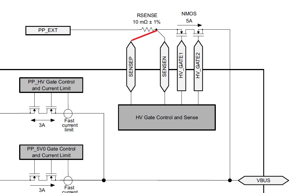
1. In TPS65982 datasheet explains 2 type of connection for SENSEP and SENSEN. Figure 20 explains SENSEP is connected to system side of sense resister if PP_EXT is used as source. But Figure 29 explained SENSEP is connected to VBUS side if PP_EXT is used as sink. If user would like to use the device as both direction without changing connection. In the case that user would like to use  the device as both direction without changing pin connection, can user realize it?

2. Can  PP_EXT pin be connected to GND if user doesn't use Dead-battery / No-Battery supports?

Regards,
Nagata.

  • Hello Nagata-san,

    To use the PP_EXT path as either a source or a sink, connect both SENSEN and SENSEP to Vbus. If the user is not using PP_HV, you can tie it to ground. However, for PP_EXT there is no pin for it. There are two pins HV_GATE1 and HV_GATE2 that are used to turn on the external switches for PP_EXT. If PP_EXT is not being used, the HV_GATE pins can be left floating.

    Thank you,
    Eric
  • Hi, Eric -san,

    Thank you for your update.

    3.
    The BUSPOWERZ pin should be connected to GND when PP_EXT is used as sink path in dead battery condition. If user has 2 type of solution (Dead battery condition and No dead battery condition), can the BUSPOWERZ pin be connected to GND pin in both condition? 

    1-1.
    >To use the PP_EXT path as either a source or a sink, connect both SENSEN and SENSEP to Vbus
    Should user connect SENSEN and SENSEP as below?


    Regards,
    Nagata.

  • Hello Nagata-san,

    If the application requires both dead battery condition and no dead battery condition, BusPowerZ should be connected to 1.8V. Please refer to Figure 62 of the TPS65986 datasheet for more details on this.
    for using PP_EXT as both source and sink path, SENSEN and SENSEP must be connected to VBUS. In your attached image, the two SENSE pins must be to the right of the mosfets. You can see the VBUS node at the bottom right of your image.

    Thank you,
    Eric
  • Hi, Eric -san,

    TPS65986 doesn't have PP_EXT. If user would like to use PP_EXT as sink in dead battery mode in TPS65982 or 83, I guess  BUSPOWERZ should be connected to GND as explained in figure 33 in TPS65983 datasheet. Can user connect BUSPOWERZ to GND in dead battery mode or no dead battery mode? Or should user not connect BUSPOWERZ to GND in no dead battery mode?

    Regards,
    Nagata.

  • Hi Nagata-san,

    For the device to boot in dead battery mode, connect BUSPOWERZ to 1.8V. If connected to 1.8V the device can also boot without being in dead battery mode or if it is externally powered.

    Thank you,
    Eric