This thread has been locked.

If you have a related question, please click the "Ask a related question" button in the top right corner. The newly created question will be automatically linked to this question.

TUSB546-DCI: DP 1.4

Part Number: TUSB546-DCI
Other Parts Discussed in Thread: DP141RLJEVM

Hi, 

I would to design a DisplayPort extender PCB which includes TUSB546-DCI linear redriver which is suitable for DP1.4 application. 

The following block diagram illustrates my target design which is very similar with the DP141RLJEVM DP141Evaluation Module Board(which support DP 1.3).

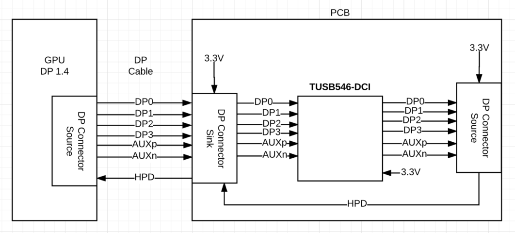
Firstly, I would like to ask if it is possible to achieve what is illustated on the block diagram with the TUSB546-DCI.
Secondly, on the datasheet(page 17)  states the following:

After power-up (VCC from 0 V to 3.3 V), the TUSB546-DCI defaults to USB3.1 mode. The USB PD controller upon detecting no device attached to Type-C port or USB3.1 operation not required by attached device must take TUSB546-DCI out of USB3.1 mode by transitioning the CTL0 pin from L to H and back to L.

In my application i plan to configure the device using GPIO mode. In addition, i don't use any USB PD controller. would this be a problem?
Would i need to transition the CTL0 pin from L to H and back to L? (assuming that the TUSB546-DCI CONFIGURATION would be set to 4 Lane DP - No Flip)

CTL1 PIN (H)
CTL0 PIN (L)
FLIP PIN  (L)

Thank you very much!!


Best Regards,
Kostas


  • Hi Kostas,

    There is an application note to configure TUSB546-DCI for DP applications, please review it

    http://www.ti.com/lit/pdf/slla365

    Regards

  • Hi Moises,

    Thank you. The DP application documentation is very clear.

    I have couple of questions though.

    In the Sink application case, the documentation states the following:
    The AUXP/N from DisplayPort receptacle should be routed directly to TUSB546-DCI and then to DisplayPort sink through 100 nF AC capacitor. The TUSB546-DCI SBU1 and SBU2 pins should be left unconnected.

    1. How this can be routed on the PCB? A stub on the AUX differential pair won't be created?

    2. On the schematics side it is shown that a 0 ohm resistor is used instead of a 100nF AC capacitor. Are the 100nF AC caps needed on the AUX signals? If AC caps are used in the GPU device will i need to add more AC caps on the PCB which includes the redriver?

    3. Figure 5(page 5) shows that the AUXp signal is pulled high with 1MOhm res and AUXn is pulled low with 1MOhm res. On the schematics side(page 8) this is reversed. AUXp signal is pulled low with 100kOhm res and AUXn is pulled high with 100kOhm res. However the resistors are shown are not connected NC.
    Which polarity shall i use? Are the pulled high and pulled low res needed?

    4.Page 8 on the schematics states the following: Populate with 100uF if DP source does not have AC capacitors at its output.
    I think it capacitor value should be 100nF.

    Lastly could you please provide the footprint for the TUSB546-DCI in Altium Designer?

    Thank you very much!!!

    Best Regards,
    Kostas

  • Hi Kostas,

    AUX connection has slight differences between source and sink application, you have to follow the proper configuration for the application, I'l answer your questions for a sink application(on display side).

    1)
    Yes, there will be some stub in AUX path, yo na make it as short as possible.
    AUX data rate is 1Mbps and FAUX is 720Mbps, AUX transactions are not that long and are not active all the time, a small stub won't have problems.

    2) Follow figure 5, the one with 1M pull-up on AUXp and 1M pull-down on AUXn, the place 100nF caps between pull-up/pull-down and DP receiver.

    3) If this is a sink application follow figure 5, this configuration is required by DP specification.

    4) The schematic has the option to populate 100nF capacitors if needed, these capacitor should be place on GPU side. the EVM has the placeholder for testing, a sink application won't need them because the source side will have them.


    I'll send available files by email.

    Regards
  • Thank you very much Moises. Your support couldn't be more better!!!

     According to the TUSB546-DCI datasheet the typical Average active power for 4 Lane DP Only is 660mW. Do you know what is the maximum or peak power for 4 Lane DP Only?

    Lastly, in case TUSB546-DCI is used for sink aplication, how long can the passive cable which will be connected to the monitor display can be? 
    On the other hand, if an active cable is connected will it cause any issues(assuming that the signals have been redrived by the TUSB546-DCI)? 


    Best Regards,
    Kostas

  • Hello Kostas,

    The maximum power is about 750mW. The active cables should not be an issue since this is a linear re-driver. Meanwhile, the cable length highly depends on the cable quality.

    Regards,
    Diego.