This thread has been locked.

If you have a related question, please click the "Ask a related question" button in the top right corner. The newly created question will be automatically linked to this question.

SN65HVD3082E: Ground floating issue

Part Number: SN65HVD3082E
Other Parts Discussed in Thread: SN65HVD1786

Hi  Experts:

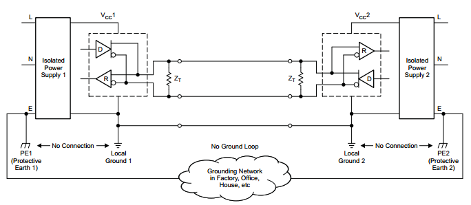
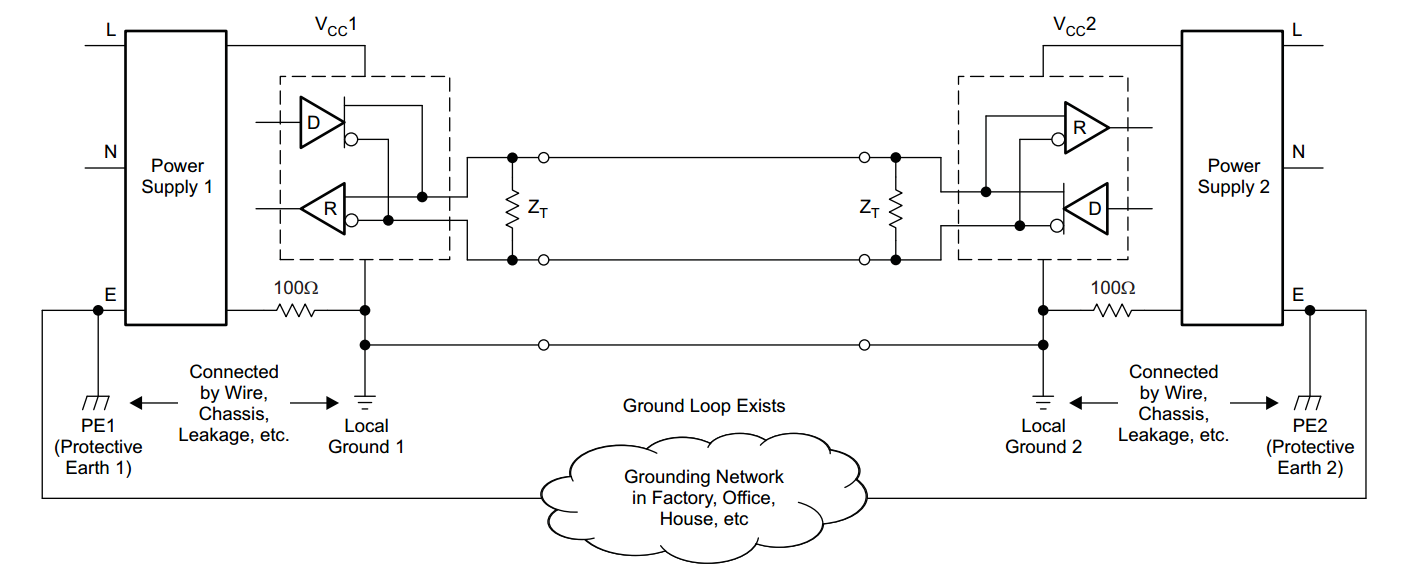
                I have a questions about he RS-485 Transceiver's application. My customer used the SN65HVD3082E for the RS-485 transceiver in their project. But the cable is the twisted-pair with the A,B signal, so they can't connect the Ground of the transceiver to other 485 devices. It means that there is the potential risk of the 

common-mode voltage from other 485 device they can't sustain because of the floating ground issue.

               So my questions are :

              1)   Is it possible to damage to SN65HVD3082E because of the unpredicted common-mode voltage (>=14V) ?

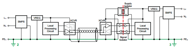
              2)   Is there solution to optimize such as PCB layout , External circuit ?  Customer has added an isolation between the 485 ground to the system ground .  

Thanks! 

  • Hi Jason,

    Yes, it is possible to damage the device if it is subjected to greater than 14V. Your customer could look in to getting a part with a wider common mode range such as the SN65HVD21A with a common mode of -20 to 25, or a SN65HVD1786 if you need protection above 20V (the part will not operate above 20V but will return to normal after the common mode voltage goes down). But if ground potential difference is a big concern, you will need a ground wire of some sorts. The ground wire could be a shielding around the twisted pair tied to ground, or an actual third wire. I have attached some diagrams to help and cover some different options. Would you be able to share some schematics of your customers system?

    First off it sound like your customer has done something close to this just with out the ground wire. I feel like this might be the easiest to implement on their system

    or for non isolated power supplies. The resistors are there to limit the possible current in  the ground loop.

    A more difficult way is to build the system is like this. The up side to this system is that it can withstand a few kilo-volts of common mode voltage and is very robust. In this setup all but one node would need isolation.

    I hope this is helpful.

    Regards,

    Daniel Noel

  • Hi  Daniel:

                  Thanks for your comments, and I am trying to get customer's schematic review.

                  If customer has used the Option3 which isolated the power supply and the signal . Do they still need the higher maximum rating of the common-mode of the

    RS-485 transceiver such as SN65HVD3082E.

                  As my logic , even isolating between the transceiver and the system , it is still possible to damage the transceiver if greater than the 14V.


  • With Option 3, the transceiver on the right uses the ground of the left device, and then translates to the possibly-different level of the actual device. This implies that there is almost no common-mode voltage and that you can use a device with a lower maximum rating, but it does not help you because it still needs a ground wire.

    All three options use three wires. (In option 3, you could omit the isolated supply by using a fourth wire to power the right transceiver from the other end.)

    Adding overvoltage protection to your circuits might be a good idea, but that just prevents the transceivers from being damaged, it does not make the communication work if the ground level difference is outside the allowed range.

    You can get away with two wires only if you ensure that the common-mode voltage is limited. If at all possible, find a third wire (or shield, or anything).

    Furthermore, AN-1057 Ten Ways to Bulletproof RS-485 Interfaces (SNLA049) says:

    Although the potential difference between the data-pair conductors determines the signal without officially involving ground, the bus needs a ground wire to provide a return path for induced common-mode noise and currents, such as the receivers' input current. A typical mistake is to connect two nodes with only two wires. If you do this, the system may radiate high levels of EMI, because the common-mode return current finds its way back to the source, regardless of where the loop takes it. An intentional ground provides a low-impedance path in a known location, thus reducing emissions.

    Also see section 11 of The RS-485 Design Guide (SLLA272).

  • Hi Jason,


    If the customer uses option 3 they could use the SN65HVD3082E and just like Clemens said option 3 has almost no common-mode voltage so there is very little of a risk of damaging the part with different ground potentials, but requires a ground wire as with all the other system solutions.

    The suggestion of getting a part with a wider common mode range such as the SN65HVD21A is if the customer cannot ensure a ±14V common mode voltage but could keep it to ±20V someway,or more specifically –20 V to 25 V, which is still risky if they are expecting that wide of difference in ground potentials.

    SN65HVD1786 is for, if the customer expects common mode voltage to fluctuate for a few moments and then go back to normal, and for the system to operate normally after the common mode voltage has decreased back to a tolerable range for the device, but the part will not function when the ground potential are this high.

    And like Clements pointed out the customer may want to impalement some transient voltage protection such as TVS diodes.


    Regards,
    Daniel Noel
  • Hi  Daniel & Clements:

                      Thanks for your detail answer.

                      I misunderstand the option3's ground connection before , and customer used the option3 without the Ground connection between two RS-485 transceiver,

    just isolated the power and signal between transceiver and the internal system.

                      Let me summary your comments:

                     1) The best way is to connect the ground between two RS 485 transceiver to decrease the risk of the difference common-mode voltage.

                      2) If customer can't accept the 1st suggestion , the SN65HVD1786 or the SN65HVD21A might be the better choice because of  subjecting the  wider common-mode voltage.

    Thanks!