This thread has been locked.

If you have a related question, please click the "Ask a related question" button in the top right corner. The newly created question will be automatically linked to this question.

AM26C31: when I use AM26C31 and AM26C32 to transmit PWM signal, I Isolated this two chip GND,they are damage,I want to know how to solve this problem

Part Number: AM26C31
Other Parts Discussed in Thread: AM26C32

1、I am using DSP to produce PWM control signal, the signal into a SN74LV245 , Enhance signal driving ability. Then after  the  AM26C31  change the single-ended signal  to differential signal. Through a cable, the PWM into another  board , on this board, I use AM26C32 change the differential signal to single .When I connect the GND to each other , They are working properly , like  this:

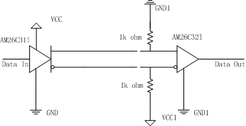
2、For some reason ,I must isolate the GND for AM26C31 and AM26C32, but the AM26C32 always be damaged .like this:


3、I want to know whether I use this chip like this may case some problems?Please give me some advice,Thanks a lot! Look forward to your reply.

  • Hello,

    When you separate the two grounds, how much of a voltage offset do you expect between them? Voltage offsets between the grounds will result in a shift in the voltages seen by the receiver (AM26C32), and if these voltages exceed the absolute maximum range of the corresponding pin then damage may occur.

    Max
  • Hi Max:

          Do you have any good suggestions to protect the receiver (AM26C32)?please give me the AM26C32 and AM26C31  typical applied circui.Thanks a lot .

  • Sorry for the delay - I was out of office last week. If the voltage difference is relatively small, then you could insert some series resistances between the transmitter and receiver. You need to be careful not to make them too large, though, since they can also lead to attenuation of the signal and a low-pass filtering effect (due to the combination of the resistances and the parasitic/load capacitances). A better solution that could work for much larger voltage offsets is to connect the grounds of the two transceivers but then use a digital isolator to isolate the logic interfaces. For more information on that approach, please see this application note (Section 11):

    www.ti.com/.../slla272c.pdf

    Best regards,
    Max