This thread has been locked.

If you have a related question, please click the "Ask a related question" button in the top right corner. The newly created question will be automatically linked to this question.

P82B96: Undershoot on P82B96

Part Number: P82B96


Hello,

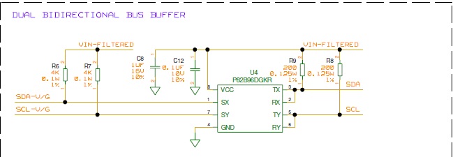
We are using P82B96 in our design to have I2C communication over 6m cable. We are seeing 1V undershoot and we inserted a BAT54A diode as suggested in datasheet, but still we are seeing 0.5V undershoot. Please find the attached images for the same. PLease suggest how can we avoid the Undershoot and ringing effect.

  • Hello Kiran,

    You have 6m of cable so that means you have a lot of inductance.  So it isn't unexpected that you will see this undershoot.  It this undershoot causing a problem?  In I2C you monitor the bits on the center of the high clock pulse. 

    The root cause of the undershoot is the size of the inductance and the speed at which the fet pulls the line to ground from Vcc.  You have no direct control of the FET's gate, but you could put some series resistance to dampen it but then you might have Vol issues.  You could try going to a thicker gauge wire to reduce inductance.  You could also try a snubber circuit tuned for the high frequency undershoot. 

    Is this undershoot causing a communications problem? 

    -Francis Houde

  •  Hello Francis,

    No, the undershoot is not causing any problem for communication but out concern is damage to P82B96 IC. As suggested in datasheet, we inserted a BAT54 Schottky diode but still we are seeing 500mA. We tried connecting 47 ohm series resistor but also we didnot see any significant reduction in Undershoot. Can you please suggest diode which we can use to dampen Undershoot or resistor value to put in series.

    Please find the attached Schematic for reference.


    Thanks,
    Kiran

  • Hello Kiran,
    What do you mean that you are seeing 500mA? It this what is being seen in the part or on the rail? Where is the current going? Can you explain?
    -Francis Houde
  • Hello Houde,

    With respect to above question, it is 500mV. Sorry, How can we reduce it.
  • Hello Kiran,

    Assuming that you have the Schottky diodes on the lines, you will not damage the P82B95 parts.   The main concern you have without the external diodes is that the internal diodes of the P82B95 could be forward biased and current could go into the part.   The internal diodes of the P82B95 will have much higher Vf than a Schottky diode. Thus having the external Schottky diode makes sure it conduct before the P82B96's internal diode do, therefore there is no risk of damaging the P82B95. The only way that you can truly reduce the size of the clamping voltage due to the inductance and turn off speed is to have an even lower Vf (forward breakdown voltage). This is accomplished by going to a larger (higher current) Schottky diode.  

     I have shown you a plot of Vf vs. If (forward current).  this shows the difference due to size. 

    Please let me know if there is a goal for the max reverse voltage and what you hope to accomplish with that clamping. 

    -Francis Houde

  • Hello Houde,

    Thanks for your continuous support. The problem I am facing is that we have already fabricated PCBs and Mechanical enclosure for the same. I am able to accommodate BAT54 (SOT23) package in my existing PCB, without any change in its dimensions (and hence no change in Mechanical Enclosure). I understand your explanation about internal clamping diode conducting, but I couldnt find information about Vf of internal clamping diode of P82B96. Can you please help me get this data, so that I can document it and explain it to review panel during design review.

    My main concern is, even with BAT54 I am getting 500mV of undershoot which is more than Absolute maximum specified for IC (-0.3V). I am worried about field failures because of repeated undershoot pulse.

    Thanks,
    Kiran.A
  • Hello Kiran,

    Have you tried a BAT54C?  It has two parallel diodes in the same package.  You may also want to look at lower voltage schottky diodes, they will likely have a lower Vf. 

    -Francis Houde

  • Hello Kiran,
    I went to one of the many distributors and found lots of schottky diodes that are footprint compatible and have the needed Vf for your given load. Just do a search and sort by load, SOT-23, and Vf. Remember to look at Vf vs If curve to see it is meets your requirements.
    -Francis Houde
  • Hello Houde,

    We did a search on Mouser and Digikey for the SOT-23, we couldn't find much. Can you please suggest diode part which we can use.
  • Hello Kiran,

    You have to look at the datasheets and look at the plots.  You can't use the Vf listed in the datasheet as a search parameter.  That Vf is references at the max If current.  You won't be using the max If in the application.    

    Here is an example with datasheet:

    BAT1000

    https://www.diodes.com/assets/Datasheets/ds30245.pdf

    There are lots of parts that will work.  The only place you might have issues is at cold, Vf goes up with cold. 

    -Francis Houde

  • Hello Kiran again,

    One more note.  Makes sure you are making the Vf measurement right at the part and also make sure you are NOT using sloppy ground clips to make the measurement.  Use small ground loop or diff probe to measure what is truly being seen by the part and not picked up noise by the scopes ground lead.

    here is a post from another E2E forum that explains how to take accurate noise measurements.

    https://e2e.ti.com/support/power_management/simple_switcher/w/simple_switcher_wiki/2243.understanding-measuring-and-reducing-output-voltage-ripple

    -Francis Houde

  • Hi Kiran,

    I've found several parts that could work (these Vf are rated at 0.1 A)

    BAT1000
    Vf = 235 mV
    Diodes Inc.
    www.farnell.com/.../1915787.pdf

    FYV0704S
    Vf = 290 mV
    Fairshild Semi
    www.farnell.com/.../1915787.pdf

    DB3X209K0L
    Panasonic
    Vf = 300 mV
    www.farnell.com/.../1912090.pdf

    ZHCS2000
    Diodes Inc.
    Vf = 200 mV
    www.diodes.com/.../ZHCS2000.pdf

    BAT68
    Infineion
    Vf = 275 mV
    www.mouser.com/.../bat68series-89099.pdf