Part Number: SN65DSI83
Tool/software: Linux
***Issue Summary:
With valid DSI input data to the SN65DSI83 and properly initialized chip sequence, the SN65DSI83 does not output LVDS data.
**Background/configuration as follows:
Custom Hardware using microsom with Qualcomm Snapdragon 805/APQ8084 processor. (Baseline software/hardware Inforce 6501)
The APQ8084 processor i2c bus and DSI output (4 data lanes + 1 clock lane) a connected to the SN65DSI83.
The SN65DSI83 is connected to our custom glue logic with panel.
The DB_APQ8064_DSI_Timing_Program.xlsm spreadsheet and relevant Linux driver files has been updated per lm80-p0436-4_dsi_display_porting_guide.pdf and lm80-p0598-2_apq8064e_dsi_programing_gd.pdf documents.
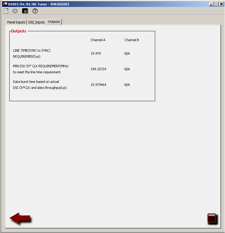
The Texas Instruments DVI Tuner 2.0 application with sllc434c supporting documentation were used to properly configure the SN65DSI83. The values in the Tuner App match the Qualcomm excel spreadsheet.
****What we've verified:
The SN65DSI83 initialization sequence is being performed per the datasheet. Specifically, we've verified timings and we've verified the LP11 state of all DSI pins prior to the enable line going high. At power on the SN65DSI83 is disabled and is enabled ~15-20 seconds after power on.
We see the snapdragon output what appears to be valid DSI data coming out of 4 lanes and clock lanes at 249.32 MHz. We don't have a DSI protocol analyzer to know for sure.. The line times and frame times look correct and match the programmed values.
After Init Seq 7 the PLL is verified to be locked
Err register reads 0 (repeat and always reads 0)
Interrupts are never enabled to process errors.
The i2c writes and reads are logged to the console to verify correctness.
The LVDS output data lines have not activity, but LVDS clock is correct rate of 83.10667
If we enable the test pattern mode we see vertical bars on the display and we see activity on the LVDS data and clock lines . The datasheet does not describe the test pattern... Is this the correct test pattern generation ?
Please see the attachment of DVI tuner setup: