This thread has been locked.

If you have a related question, please click the "Ask a related question" button in the top right corner. The newly created question will be automatically linked to this question.

TPS65982: Discharge circuit of Bulk Cap for safety operation

Part Number: TPS65982

Hi Team,

I would like to know whether TPS65982 have a discharge circuit to release charged voltage at Bulk Caps. Does TPS65982 have the circuit or we need to put it anywhere on Vbus for safety?

The PD specification requires total 120uF cap on Vbus line at least but it takes a little bit long time to release 1.8mC(15V*120uF). The charge might cause some issues when attaching device which doesn't have 20V tolerant.

For example when connecting a other device using Type-C to A cable  immediately after disconnecting the connector from the state where power was supplied at 20 V. If the other device doesn't have 20V tolerant, it might be broken due to over voltage stress.

Regards,

Takashi Onawa 

  • Hi Onawa-san,

    I see where you are referring to the PD spec. However, the 120uF cSrcBulkShared refers to the amount of capacitance needed on the Source of VBUS when VBUS is being powered by a shared supply.

    The source of VBUS should be able to charge and discharge the capacitance within tSrcReady (285 ms) to be within spec.

    For the example you are referring to, the TPS65982 will not close the switch on VBUS if the voltage is too high or too low with the negotiated PDO.

    Thank you,

    Eric

  • Hi Eric-san,

    I wanted to know whether TPS65982 has a discharge circuit internally or not.  Sorry for my less explanation on that, My customer will use variable DC-DC architecture indicated in the link below.

    So they was annoying how to achieve the PD spec you mentioned above.

    >The source of VBUS should be able to charge and discharge the capacitance within tSrcReady (285 ms) to be within spec.

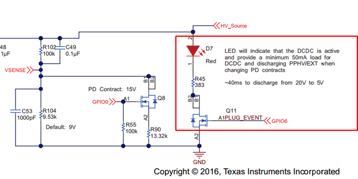
    Then, I found the discharge circuit in the schematic in the link.

    I understood this circuit is necessary to discharge on power supply side, is this correct?

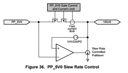
    For Type-C receptacle side, I think the function integrated in TPS65982 as below works as discharge circuit though, Am I correct?
    I didn't understand well how this function works when to switch PP_EXT to PP_5V, so It's nice if you give an additional explanation for my understanding(Because my customer will use PP_Ext and PP_5V to switch 5V, 9V, 12V, 15V and 20V using variable DCDC arch.)

    Regards,

    Takashi Onawa

  • Hi Onawa-san,

    You are correct, the circuit you included with the LED is used to discharge the capacitance on the VBUS source within the PD spec time.
    The schematic in the second image you included (Figure 36) is to control the turn on sequence of the switch. When the switch closes from PP_5V0 to VBUS an inrush of current can be experienced causing an OCP event to occur. This circuit controls that inrush current and insures the switch closes smoothly.

    Thank you,
    Eric
  • Eric-san,

    Thanks for your prompt response. I almost understood.

    Let me confirm the "integrated active pulldown on VBUS" at the end.
    The two points are unclear for me.
    1. Will the pull-down function be also active in PP_EXT to PP_5V switching?
    2. Does this pull-down function work well if 9VPDO was set on PP_HV also?

    >When switching from PP_HV or PP_EXT to PP_5V0, PP_HV or PP_EXT must be above VSO_HV to follow the switch-over shown in Figure 35.
    >VSO_HV : 9.9V(min)
    9V PDO was not existed in first gen PD2.0 but it need to be supported in current version. I think it's difficult to belong to the sentence above in current version PD spec.

    Regards,
    Takashi Onawa
  • Hi Onawa-san,

    1. Yes, this functionally will also work when switching from PP_EXT to PP_5V.
    2. This function also works with 9VPDO on PP_HV.

    Thank you,
    Eric