Part Number: TPS65982
Hello,
We are using TPS65982 PD controller in our custom proto board and able to test Alternate Mode DP, USB Gen2 and PD Sink features.
In PD Sink feature, we are having 5# high current LEDs connected to PP_EXT rail. We can control these LEDs by controlling the FET gate pins as shown in attached snapshot.
Even we are able to control the LEDs (ON & OFF) as power our requirement.
Our requirement includes to measure the current getting sunk. We used Aardvark programmer (I2C) to access the PD controller registers. Even we are able to read the voltages @ VBUS, SENSEP, GPIOs etc. But, if I read I_PP_EXT (current through PP_EXT path), then always it will be 0A using TI Utility. If I measure using digital multi-meter then with 12V PP_EXT, the current consumption is ~90mA.
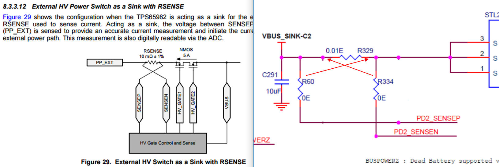
I have also attached the SENSE resistor schematics for your reference. I understand that current through PP_HV can not be read via ADC when it is sinking. But, datasheet says that I_PP_EXT can be read if 10mohm R(Sense) is used. [8.3.3.12 External HV Power Switch as a Sink with RSENSE]
We have used "RL0805FR-7W0R01L" as sense resistor.
Please suggest us how to proceed further to digitally read the current using internal ADC.
/cfs-file/__key/communityserver-discussions-components-files/138/8512.PP_5F00_EXT_5F00_SNK.zip
With Regards,
Hariprasad Bhat