


Part Number: TS3USB221
Other Parts Discussed in Thread: TPS22930A
Hello,
I am using this part to take a USB 2.0 Type-A connector (USB thumb drive connected here) and switch that between two micro-usb receptacles. This is so the client (Minnowboard Turbot) can load an image onto the Flash drive, and when the TS3USB221 control signal switches (remotely controlled by Minnowboard), the image from the Flash Drive can be loaded onto the SUT, and vice-versa. Here is an image of my schematic:
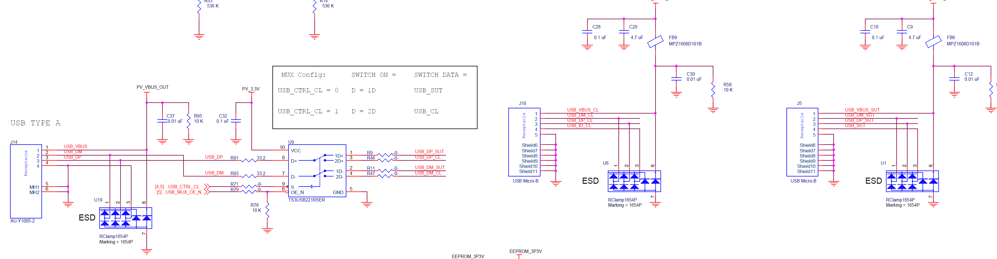
PV_VBUS_OUT is being powered using whichever micro-b differential signal is connected through the switch to the type-A Receptacle: This is done using the USB control signal and two load switches TPS22930A. This method seems to work fine, as power is always a constant 5V on the PV_VBUS_OUT line, as long as the corresponding micro-b is connected and switched on. Do you see any issues with what I've done here?
First, I enable the switch (USB_MUX_OE_N = 0) and connect through client side (USB_CTRL_CL = 1 ==> D = 2D or USB_DP = USB_DP_CL, USB_DN = USB_DN_CL). Assuming the TS3USB221 is basically a short now, the USB storage Device should be connected to the client (Minnowboard) through my board (interface board) like so:

However, when I connect the boards like this and insert the thumb drive, it seems that the thumb drive continuously tries to establish a connection to the Minnow but never does. When I remove the 33 ohm series resistance on the differential signals, and put in -0- ohm jumpers instead, the connection is established. We have always historically used 33 ohms on USB 2.0 diff pairs for EMI mitigation. And this is recommended as seen here:
https://www.fairchildsemi.com/application-notes/AN/AN-5052.pdf
Might anyone know why I am seeing this SI issues with the 33 ohm resistors populated, and a working USB connection with -0- ohm jumpers populated instead?
Thank you
