This thread has been locked.

If you have a related question, please click the "Ask a related question" button in the top right corner. The newly created question will be automatically linked to this question.

TCA9548A: i2c multiplexing problem

Part Number: TCA9548A
Other Parts Discussed in Thread: BQ3060

I´m using a TCA9548A for multiplexing i2c devices with the same adress.
this i2c devices are bq3060 IC, and the objective is to read the registers from the ICs conected in port 0 and 1.
I managed to read the IC in port 0. Also the other IC in port 1. But when I try to read both ports, first port 0 and after port 1, some times I have reading problems. The problem is when there is a port selection change in the TCA.
I have seen that when I have reading problem is because in the i2c signal sent to select the port in the TAC9548 (in "tcaselect()" , "BP_WriteReg" ) the stop bit is not send correctly. I post below the code of my application and also I attached the i2c signal when I write the port of the TCA.
My question is, why can be that sometimes, when I write in TCA9548 the stop bit is not send correctly and other times yes. When it is not send ok, it seems that the clock signal is going down just when the data is going high for the STOP bit.

i2c signal sent to TCA in order to select the port (the black marked bit is the stop bit):


My code is the next:

  tcaselect(0); 
  VoltageArray[0]=BP_ReadReg(0x09);
  SOCArray[0]=BP_ReadReg(0x0d);  
 
  tcaselect(1); 
  VoltageArray[1]=BP_ReadReg(0x09);
  SOCArray[1]=BP_ReadReg(0x0d);

void tcaselect(uint8_t i) 
{
  if (i > 7) return; 
  tmp=(1<<i);
  BP_WriteReg(0x01,tmp); 
}

void BP_WriteReg(uint8_t RegName, uint8_t RegValue)
{
  /*-------------------------------- Transmission Phase -----------------------*/
  /* Send BP_I2C START condition */
  I2C_GenerateSTART(BP_I2C, ENABLE);

  /* Test on BP_I2C EV5 and clear it */
  while (!I2C_CheckEvent(BP_I2C, I2C_EVENT_MASTER_MODE_SELECT))  /* EV5 */
  {
  }

  /* Send BP slave address for write */
  I2C_Send7bitAddress(BP_I2C, i2c_MULT_ADDR, I2C_Direction_Transmitter);

  /* Test on BP_I2C EV6 and clear it */
  while (!I2C_CheckEvent(BP_I2C, I2C_EVENT_MASTER_TRANSMITTER_MODE_SELECTED)) /* EV6 */
  {
  }

  /* Send the specified register data pointer */
    I2C_SendData(BP_I2C, (uint8_t)RegValue);

  /* Test on BP_I2C EV8 and clear it */
  while (!I2C_CheckEvent(BP_I2C, I2C_EVENT_MASTER_BYTE_TRANSMITTED)) /* EV8 */
  {
  }

  /* Send BP_I2C STOP Condition */
  I2C_GenerateSTOP(BP_I2C, ENABLE);
}

uint16_t BP_ReadReg(uint8_t RegName)
{
  __IO uint16_t RegValue = 0;

  /* Enable BP_I2C acknowledgement if it is already disabled by other function */
  I2C_AcknowledgeConfig(BP_I2C, ENABLE);

  /*--------------------------- Transmission Phase ----------------------------*/
  /* Send BP_I2C START condition */
  I2C_GenerateSTART(BP_I2C, ENABLE);

  /* Test on BP_I2C EV5 and clear it */
  while (!I2C_CheckEvent(BP_I2C, I2C_EVENT_MASTER_MODE_SELECT))  /* EV5 */
  {
  }

  /* Send STBP slave address for write */
  I2C_Send7bitAddress(BP_I2C, BP_ADDR, I2C_Direction_Transmitter);

  /* Test on BP_I2C EV6 and clear it */
  while (!I2C_CheckEvent(BP_I2C, I2C_EVENT_MASTER_TRANSMITTER_MODE_SELECTED)) /* EV6 */
  {
  }

  /* Send the specified register data pointer */
  I2C_SendData(BP_I2C, RegName);

  /* Test on BP_I2C EV8 and clear it */
  while (!I2C_CheckEvent(BP_I2C, I2C_EVENT_MASTER_BYTE_TRANSMITTED)) /* EV8 */
  {
  }
  /*------------------------------ Reception Phase ----------------------------*/
  /* Send Re-STRAT condition */
  I2C_GenerateSTART(BP_I2C, ENABLE);

  /* Test on EV5 and clear it */
  while (!I2C_CheckEvent(BP_I2C, I2C_EVENT_MASTER_MODE_SELECT))  /* EV5 */
  {
  }

  /* Send BP slave address for read */
  I2C_Send7bitAddress(BP_I2C, BP_ADDR, I2C_Direction_Receiver);

  /* Test on EV6 and clear it */
  while (!I2C_CheckEvent(BP_I2C, I2C_EVENT_MASTER_RECEIVER_MODE_SELECTED))  /* EV6 */
  {
  }

  /* Test on EV7 and clear it */
  while (!I2C_CheckEvent(BP_I2C, I2C_EVENT_MASTER_BYTE_RECEIVED))  /* EV7 */
  {
  }

  /* Store BP_I2C received data */
  RegValue = (uint16_t)(I2C_ReceiveData(BP_I2C));       
  
  /* Disable BP_I2C acknowledgement */
  I2C_AcknowledgeConfig(BP_I2C, DISABLE);

  /* Send BP_I2C STOP Condition */
  I2C_GenerateSTOP(BP_I2C, ENABLE);

  /* Test on RXNE flag */
  while (I2C_GetFlagStatus(BP_I2C, I2C_FLAG_RXNE) == RESET)
  {}

  /* Store BP_I2C received data */
  RegValue|=(I2C_ReceiveData(BP_I2C) << 8);       
  
  /* Return register value */
  return (RegValue);
}

  • Hello Ekiuser,

    What device are you using to control the TCA9548A?  Is it one of TI's?  If so that I can move this post to their forum to help you debug you code.  We really only support the hardware.  It is clear to see the stop condition isn't being done properly by the master. 

    -Francis Houde

  • Dear Francis,

    No, I´m afraid that it´s not a TI´s controller, I´m working with a ST microcontroller.

    But, the function to select one port with "writereg" function seem to be ok. If I only connect 1 i2c device in any of the TCA9548A port, I can read properly any i2c register of the connected device. If I only select 1 port I have no problem.
    The problem comes if I want to switch from one port to other port in order to read 2 different i2c devices connected to TCA ports. Coul it be HW problem?
  • Hello Ekiuser,
    Do you have the schematics of your system? I want to look at it to make sure I know how everything is connected.

    You are switching in and out capacitive loading on the bus which might be the problem. You may want to put short delays after you set the stop condition before you try and communicate. This is just a guess at this point, but might be worth trying out.
    -Francis Houde
  • Hi Francis,

    I managed the system to work with no change in code. About what you asked me Francis, I don´t have the schematic of the system yet and I also tried to put short delays as you suggested but it didn´t work.

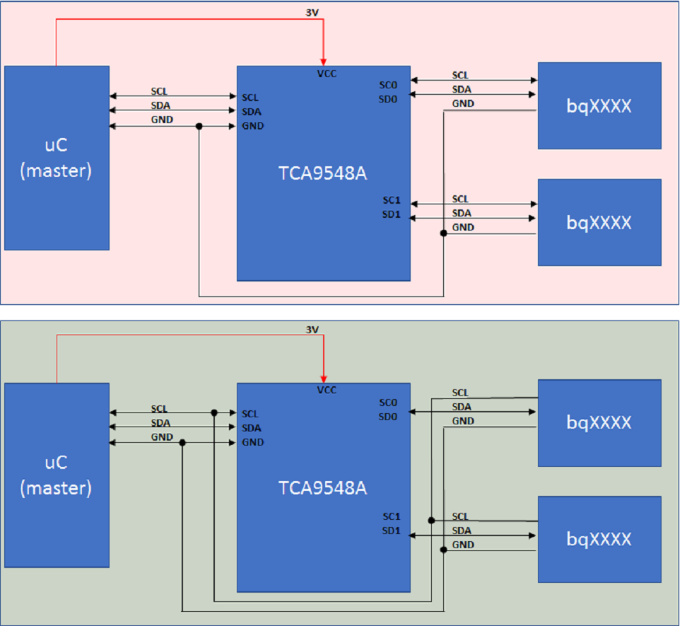
    I put all the i2c communication clocks together; the master i2c CLK signal together with the slaves i2c clocks (Port 0 slave and Port 1 slave). Now it works fine but I don´t really understand why. As far as I have seen in the datasheet, in this TCA9548A, it is supposed that the master i2c has to be connected to SLC, SDA pins; then, the slave i2c in port 0 has to be connected to SCL0 and SDA0 pins and the slave i2c in port 1 has to be connected to pins SCL1, SDA1. By the way, all the GNDs are connected together. In this way, my system didn´t work (the problem is the one I explained before). I have to move SCL0 and SCL1 from TCA pins and connect with SCL master pin.
    Are the connections correct? COuld someone explain me this?

    Thank you ini advance!
  • Hello Ekiuser,
    I am at a lost. I would really like to see a schematic to understand what is going on. This really doesn't makes sense. What is sequence for sending I2C commands? Also, do you have a picture of your setup and information about how the busses are connected? harness? board to board?
    -Francis Houde
  • In the image added the i2c schematic is shown.
    In the first schematics, as I have expalined, each slave (each bq3060) SDA and SCL is connected to TCA port 0 and port 1. With this scheme, the system doesn´t work correctly.
    In the second schematics, all the clocks are connected together and the system works fine.

  • Hello Ekiuser,
    I know this is probably a stupid question, but do you have pullups on all the channels for both SC and SD and if so what are the values? Have you verified with multimeter? Are you writing a 3h to the control register then do a stop condition before you try to communicate to either of the bq parts? I know you probably already did all this but I am just trying to make sure I am not missing anything.
    Francis Houde
  • Hello Ekiuser,
    Looking at the waveforms at the beginning of the post it looks like you are only turning on B1 not B1 and B0, you are only sending 0x02h. Was this intentional?
    -Francis Houde
  • Hello Francis,

    Yes, I have pull up resistors in each SC, SD port. In the master, the pull-up resistors are 4k7 but I also tried with 10k.

    About the communications sequence, as you can see in the code, first, I send the control byte to the master to select the port. This control byte finishes with the stop condition. Then, I read a register from the slave (bq in port 0 or 1). You can check this in the code I sent in the first posts.

    In order to select port 0, I turn on only B0 and to select port 1 B1. In case I want to select port 2 I only turn on B2. This is correct, isn´t is?

    Thank you!

  • Hi Ekiuser,

    (Francis is out of office this week, and so I am taking a look into this issue.)

    You are right that only B0 needs to be set to turn on port 0, only B1 needs to be set to turn on port 1, etc.

    Is there a way you can verify the voltage on the port that is being activated immediately before it becomes enabled? Is there any way it could be low rather than pulled high? It looks like in the "not OK" case, the clock line is briefly pulled low as soon as the stop condition is registered (which is when the channel is enabled). It is difficult to tell on this time scale, though - it would be useful to zoom in on the stop condition to get a better understanding of when exactly the clock transition takes place.

    Also (just for my understanding) - are you always disabling one channel at the same time you are enabling another one, or do you follow a "make before break" (turn on the new channel, then turn off the old one) or "break before make" (turn off the current channel, then turn on the new channel) procedure? I'm not sure it would make a difference either way, but I wanted to ask anyway to help give some context to the waveforms you provided.

    Regards,
    Max