This thread has been locked.

If you have a related question, please click the "Ask a related question" button in the top right corner. The newly created question will be automatically linked to this question.

SN65DSI85: SN65DSI Test Pattern and uncorrectable ECC error

Part Number: SN65DSI85

Hi team,

My customer BOE is evaluating SN65DSI85, they have two questions about this device as below. the attached is sch and reg setting, would you please kindly help? thanks.

1. in test mode,  what is the test pattern look like? they want to compare it with their test result

2. in normal mode, they would read 0x20 from CSR 0xE5, indicate uncorrectable ECC error. would you please suggest the possbile cause of ECC error? will power on sequence be a problem? 

KevinDSI LVDS.zip

  • Hello Kevin,

    The SN65DSI85 seems to be set up correctly in the schematics.

    Could you please use DSI Tuner to configure the device?  You can  export the .dsi file (or take some screen shots). It will help me to understand your set up easily.  I will also need you to share the panel datasheet to confirm the configured parameters.

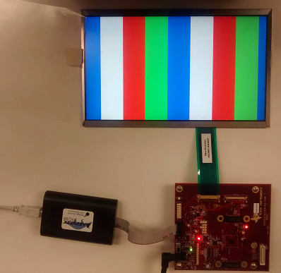
    This is the pattern that the DSI85 should display.

    The t may have been set during the initial setup. You have to check if this bit is being set back to 1 after it’s cleared. If you continue detecting the error, the DSI input may be having a signal integrity issue.You need to check timing on DSIA interface (setup/hold).  Maybe you can change DSI85 RXEQ level to see if errors go away.

    Regards

  • Hi Joel,

    thanks for your reply,  please check the .DSI setting in attached file DSI_0516.zip.

    customer don't have datasheet for the panel yet, below is there system block diagram and reslution/blanking time setting.

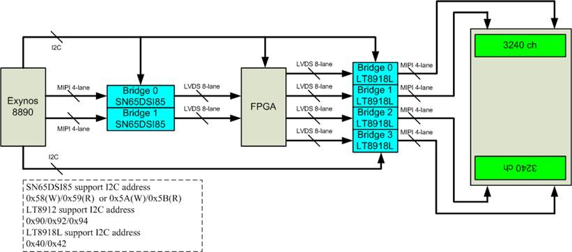
     8890 output a video stream with 2160*2400 resolution, 24 bit color depth. The two MIPI port handle left and right half of the image seperately, so it is 1080*2400 resolution for each MIPI port. Each MIPI output from 8890 is connect to a SN65DSI85. SN65DSI85 is set for 2 port LVDS, transmiting even and odd data. then the LVDS data is send to FPGA, FPGA will receive all the data in its buffer, after receiving a compete image, the data is the send to LVDS-to-MIPI bridge IC, then to panel. 

    the Blanking setting of 8890 output is VSA=2/VFP=8/VBP=6/HAS=10/HFP=120/HBP=40

    Customer have tried to connect the MIPI output from 8890 to panel directly with an adapter board, MIPI clock is 487MHz, the panel could receive the data and display the image correctly. But when they connect 8890 output to SN65DSI85, they would get a uncorrectable ECC error.

    for the CSR, customer have tried to modify 0x11 register to 0xFF, the issue is the same. do you have any other suggestion on CSR settings? 

    do you have a an measurement exmaple of DSI input singal that customer follow to test their system? 

    Could power on sequence causing this issue? 

    Kevin

    DSI_0516.zip

  • Hello Kevin,

    As per my understanding, you continue detecting the error even when it is cleared by writing a 1 value.

    Regarding the power up requirement, note that unexpected behavior may occur when the EN is asserted(transition from 0 to 1) while DSI CLK = LP00.

    Please, make sure you that all the MIPI inputs driven to LP11 (both P and N pairs of all MIPI DSI differential pairs to single ended high ~1.2V) prior to asserting EN pin

    Regards

  • Hi Joel,

    yes, we continue detecting the error even when we tried to clear it.

    for power up seq, MIPI input are driven to LP11 when EN 0->1. but their CSR reg is not controlled by the AP, so it is not sure that CSR register is initialized when DSI video steam start, will this be a problem?

    Kevin

  • Hello Kevin,

    It is recommended to program the correct register values before start the DSI video stream.
    Could they try performing the video stop and restart sequence?

    Also, verify that line time provided by the DSI video source (APU) is also correct per the recommendation generated by the DSI Tuner tool (Output tab).

    Video input timing, register configuration and the panel timing requirements all have to match up for video streaming to work without errors.

    The DSI8x does not realign timing. The line time (horizontal sync to the next horizontal sync timing from the APU) on the input is preserved when outputting onto the LVDS interface. If the line time is different from what is calculated by the tool, this will cause issues. Even if the DSI source is outputting streams in
    a burst manner, it is important for the DSI source to fill in the rest of the line time with blanking packets (or LP11) to meet the line time requirement.

    Regards,
    Joel