Other Parts Discussed in Thread: TIDA-00892, ISOW7841,
Hi everyone,
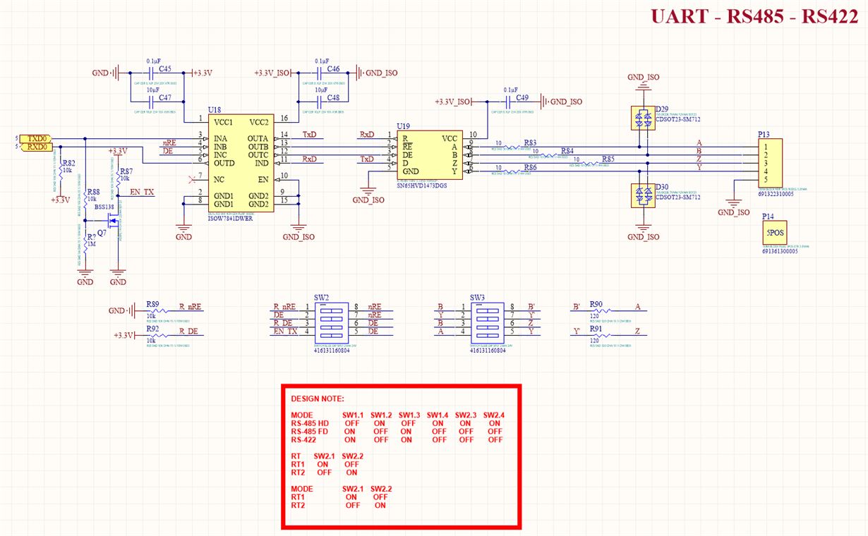
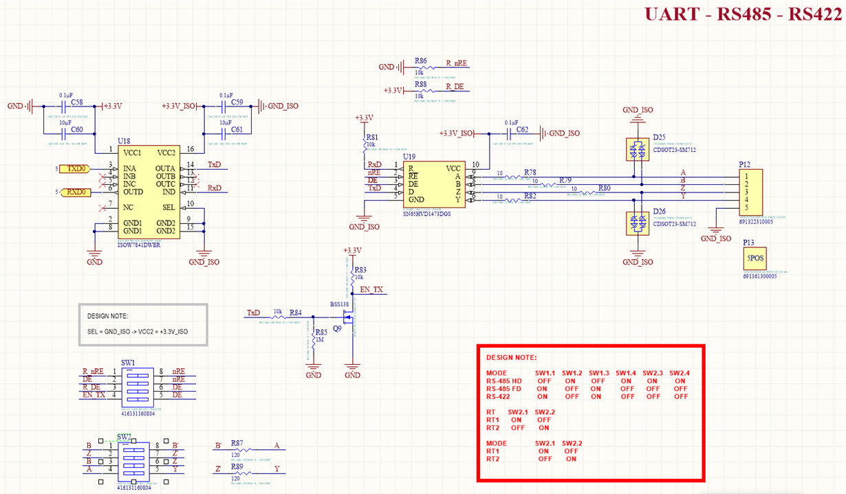
I'm checking a design, that it's basically this evaluation board with some adds to add RS-485 Half-Duplex and RS-485 Full-Duplex and RS-422 support:

I' had to build a prototype because the evaluation board was not available. I was asking some questions related to this issue in this post:

I attached my current schematic:
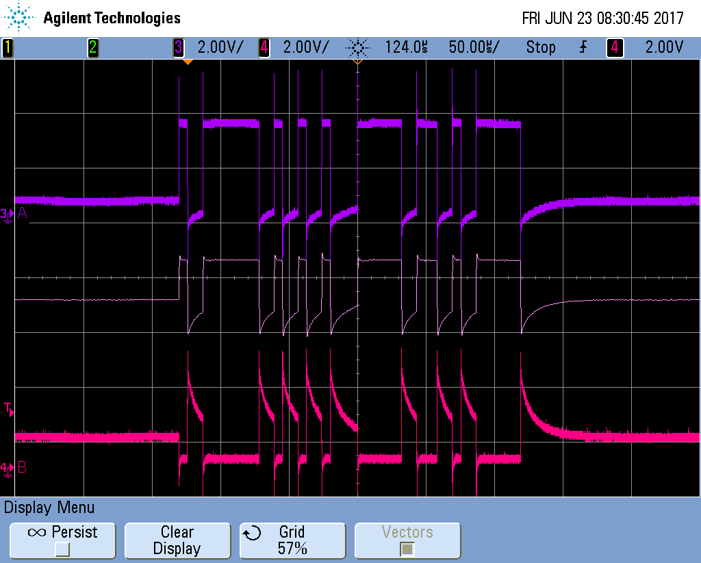
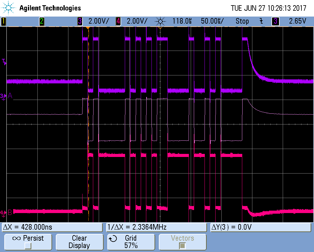
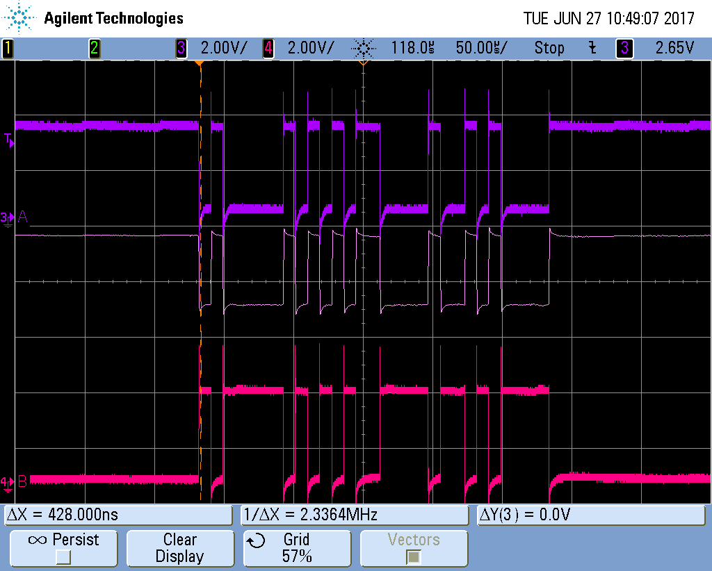
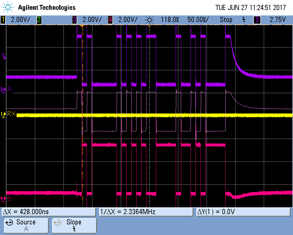
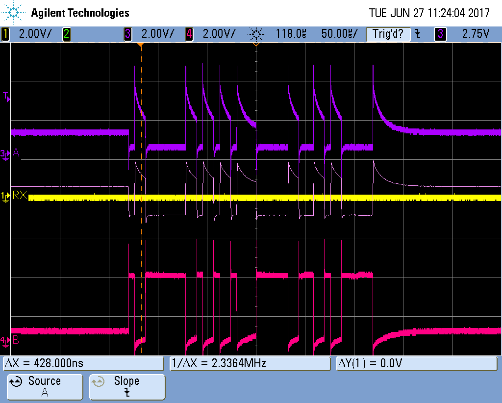
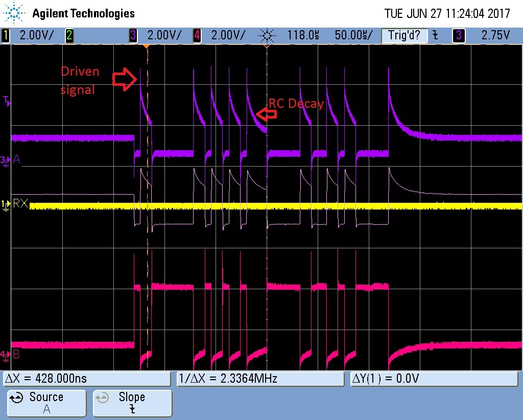
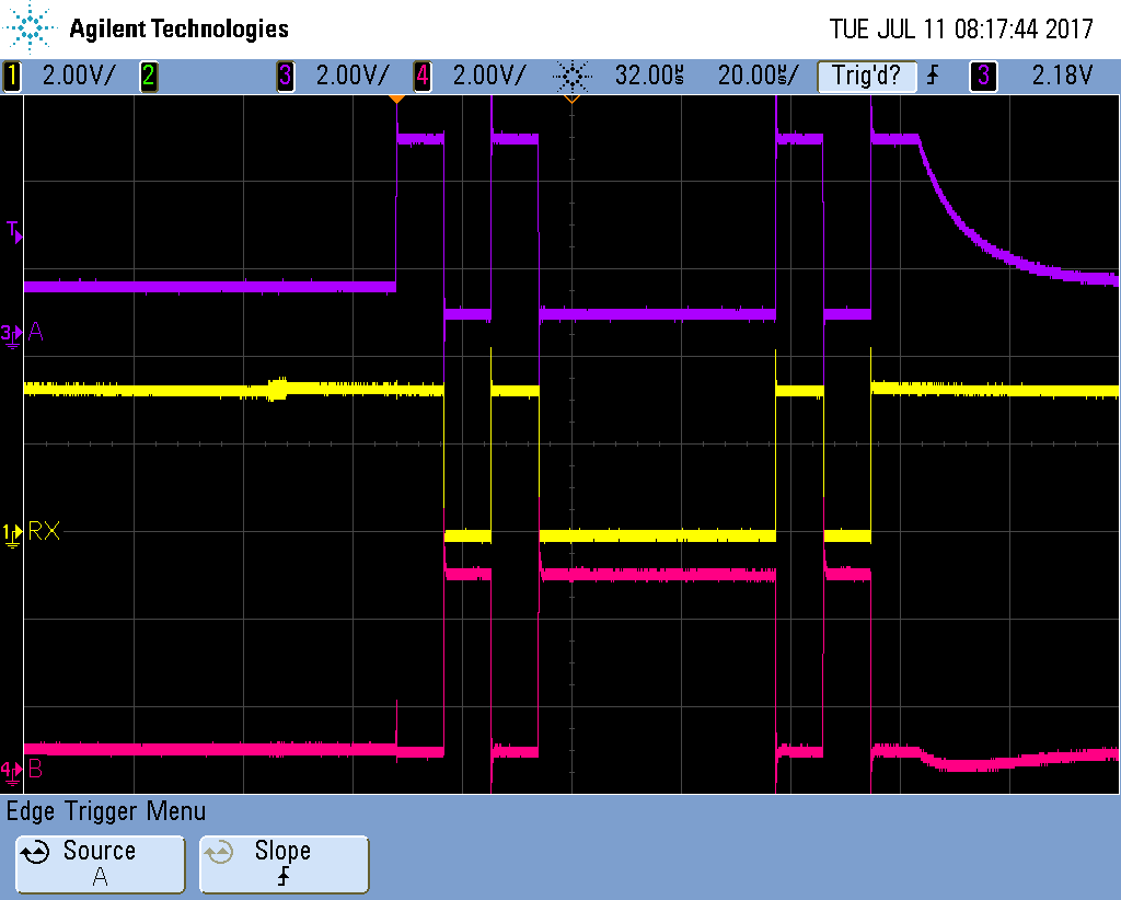
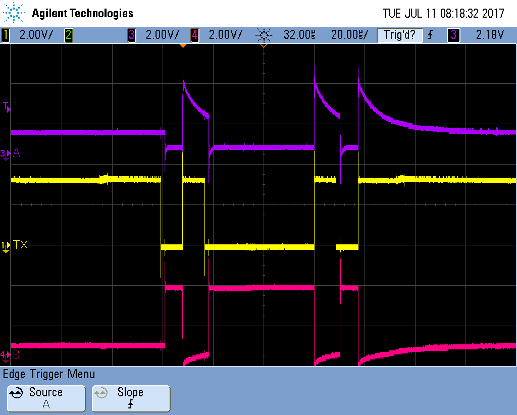
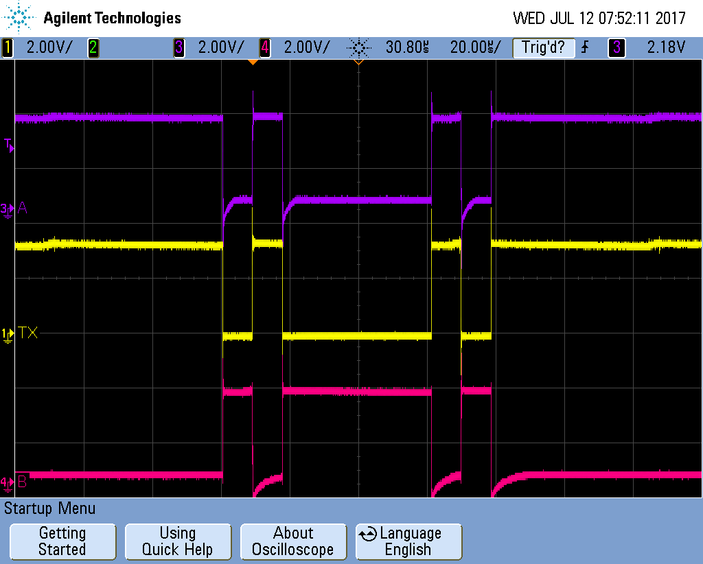
The design it's working fine until 230000 bauds. But I was analysing the waveforms and they look a bit weird. I don't have too much experience with RS-485 waveforms. I attached you the waveforms of the transmission/reception of a character "A". In this screenshot of my oscilloscope, you can see the signal A, B and in the middle is the math operation = A -B.
My questions are:
1.1.- Do you know if these waveforms are ok? The communication is working fine. I'm using the configuration in RS-485 half-duplex:
SW1.1 = OFF, SW1.2 ON, SW1.3 = OFF, SW1.4 = ON, SW2.1 = OFF, SW2.2 = ON, SW2.3 = ON, SW2.4 = ON.
SW2.1 = OFF, SW2.2 ON, SW2.3 = OFF, SW2.4 = ON, SW3.1 = OFF, SW3.2 = ON, SW3.3 = ON, SW3.4 = ON.
1.2.- I've tried to place the resistor termination of 120 Ohms and it doesn't work, so I don't place the resistor termination of 120 Ohms. I think with only 2 devices on the bus it's nor going to be necessary, isn't it?
2.- This IC SN65HVD1473DGS is failsafe biasing? or Do I have to add some extra components for that? According to this Application Note:

SN65HVD7x family and SN65HVD7X don't require an external bias resistor network. but I don't know what happen with my part number.
Best regards.


