This thread has been locked.

If you have a related question, please click the "Ask a related question" button in the top right corner. The newly created question will be automatically linked to this question.

SN65HVD72: Scope Plot of RS-485 bus transmissions

Part Number: SN65HVD72

Support Path: /Product/Development and troubleshooting/

Hi TI Support Team,

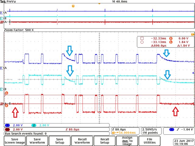
I'm currently testing on the RS-485 differential signal and observe the behaviors as shown in attached scope plot...

I was hoping to have the following demystified:

1. [Highlighted with Red Arrows] One scenario shows that the A-B signal is held HIGH when bus is inactive.
     The other scenario shows that the A-B signal is held right in the middle when bus is inactive.  
     Can anyone please advise which scenario is correct here, according to RS-485 protocol standards?

2. [Highlighted with Blue Arrows] A ramp is separately seen on A or B signal (at the same time point) in between transmissions on the bus.  The A-B signal actually cancels that ramp out.  Is this typical and acceptable on RS-485 protocol?

Thank you very much in advance for any input!

Sincerely,

Ken

  • Hi Ken,

    The RS-485 standard does not preclude either approach, however if the application involves half-duplex communication then it is necessary to disable the active RS-485 driver at some point so that other nodes can then communicate on the shared bus. (I mentioned this since I am assuming the constant "high" level is a result of the driver remaining enabled while the "ramp" behavior is a result of the driver becoming disabled/high-impedance.)

    It is normal for some ramp to occur when the driver becomes high-impedance (i.e., when the "DE" signal transitions from a high to a low state); this is no problem for RS-485 communication. This is because the bus is no longer actively driven, and its voltage will tend to drift to a mid-level bias point that is set by the receivers on the bus. Or, if "failsafe biasing" is used, the A and B lines may drift to some differential offset voltage instead - this can be useful so that idle periods are interpreted by each receiver as a prolonged "high" state rather than being indeterminate, as would be the case if the differential voltage were at 0 V. You can read more about failsafe biasing here:

    e2e.ti.com/.../get-connected-failsafe-bias-those-contentious-buses
    www.ti.com/.../slyt324.pdf

    Max