This thread has been locked.

If you have a related question, please click the "Ask a related question" button in the top right corner. The newly created question will be automatically linked to this question.

SN75LVDS83B: LVDS Output Quality

Part Number: SN75LVDS83B
Other Parts Discussed in Thread: TFP401,

Hello,

We are taking an HDMI input into a TFP401 / SN75LVDS83B combination to drive a 10.1" LVDS display.  We have our first prototype board and the circuit seems to be functioning correctly but the display is unable to recognize any input source.  Specifically, the display stays in a sort of test mode and cycles through entire RGB screens every couple of seconds or so.  I've tested the display driven by a OEM LVDS driver without problem.  The PCB follows the differential impedance calculations and the various guidelines for high speed LVDS signals.

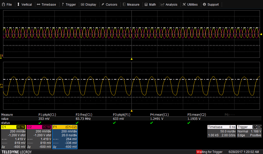
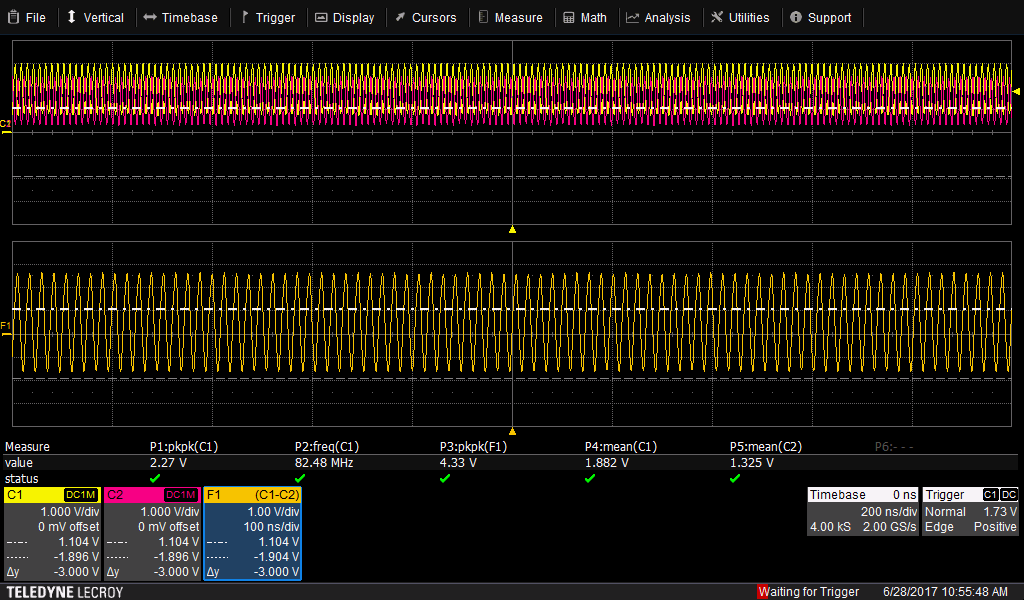
When comparing the signals from the OEM board and our prototype the voltage levels look to be quite a bit different.  Here is a capture of the clock signal from our prototype measured from the receiver side with two single ended probes.  We do not have access to a differential probe with enough bandwidth to measure this.  F1 is the math difference.  The LVDS voltage levels look sufficient with a swing of about 350mV on each line and 630mV via the difference.  The OEM board on the other hand drives their signals at a swing of over 2V.  What am I missing here?  Based on the SN75LVDS83B  output specs, it is outputting correctly and the LVDS input should be acceptable for the display.  Yet I'm still not getting any output on the display.  Thoughts?

Prototype LVDS Clock

OEM Driver Clock Signal

- Mark

  • Hello Mark,

    According to the LVDS TIA/EIA-644 spec, the LVDS driver produces a differential voltage across a 100-Ω load in the range of 247 mV to 454 mV with a typical offset voltage of 1.2 V relative to ground.

    Is the LVDS clock running at the correct panel's pixel rate?

    Could you please share your schematics?

    Regards,
    Joel
  • The display has a spec of 66.1MHz for the pixel clock nominally and both the OEM driver and our prototype is running at 83.5Mhz. I left this alone because the OEM driver board was working correctly at this speed. I actually brought over the EDID from the OEM device because it was functioning...

    Working now to alter the EDID so that the host transmits HDMI in line with displays datasheet.
  • Joel,

    After some time modifying the EDID information to match the display I was able to get everything working correctly. The EDID information I had been using had multiple extra configurations in the second block that had to be removed for the pixel clock to follow the primary Detailed Timing Descriptor. Really glad you were correct on the pixel rate and not a hardware issue. :-)

    Thanks again!
    - Mark