This thread has been locked.

If you have a related question, please click the "Ask a related question" button in the top right corner. The newly created question will be automatically linked to this question.

Linux/DS90UB964-Q1: ds90ub964 setting register problem!!!

Part Number: DS90UB964-Q1

Tool/software: Linux

hi engineer:

Now,i am useing  4 ds90ub913 + 1ds90ub964+imx6,i have some problem,please help me solve these problem ,thank you .

1:in 964 ,i have 4  Serializer link to 1 Deserialize,i want to set 4 SER_ID and SER_ALIAS_ID,but this is only one register,how to distinguish 4 Serializer .

2.when i want to set register in 964, do you have  sequence of configuration registers,

3.when i want to set  ‘#Patgen Fixed Colorbar 1280x720p30’ to test the 964, do i need set other register? My configuration is as follows

WriteI2C(0x32,0x01) # CSI0 sel and CSI0 enable
WriteI2C(0x33,0x01)
WriteI2C(0xB0,0x00) # CSI0 sel and CSI0 enable
WriteI2C(0xB1,0x01) # PGEN_CTL
WriteI2C(0xB2,0x01)
WriteI2C(0xB1,0x02) # PGEN_CFG
WriteI2C(0xB2,0x33)
WriteI2C(0xB1,0x03) # PGEN_CSI_DI
WriteI2C(0xB2,0x24)
WriteI2C(0xB1,0x04) # PGEN_LINE_SIZE1
WriteI2C(0xB2,0x0F)
WriteI2C(0xB1,0x05) # PGEN_LINE_SIZE0
WriteI2C(0xB2,0x00)
WriteI2C(0xB1,0x06) # PGEN_BAR_SIZE1
WriteI2C(0xB2,0x01)
WriteI2C(0xB1,0x07) # PGEN_BAR_SIZE0
WriteI2C(0xB2,0xE0)
WriteI2C(0xB1,0x08) # PGEN_ACT_LPF1
WriteI2C(0xB2,0x02)
WriteI2C(0xB1,0x09) # PGEN_ACT_LPF0
WriteI2C(0xB2,0xD0)
WriteI2C(0xB1,0x0A) # PGEN_TOT_LPF1
WriteI2C(0xB2,0x04)
WriteI2C(0xB1,0x0B) # PGEN_TOT_LPF0
WriteI2C(0xB2,0x1A)
WriteI2C(0xB1,0x0C) # PGEN_LINE_PD1
WriteI2C(0xB2,0x0C)
WriteI2C(0xB1,0x0D) # PGEN_LINE_PD0
WriteI2C(0xB2,0x67)
WriteI2C(0xB1,0x0E) # PGEN_VBP
WriteI2C(0xB2,0x21)
WriteI2C(0xB1,0x0F) # PGEN_VFP
WriteI2C(0xB2,0x0A)
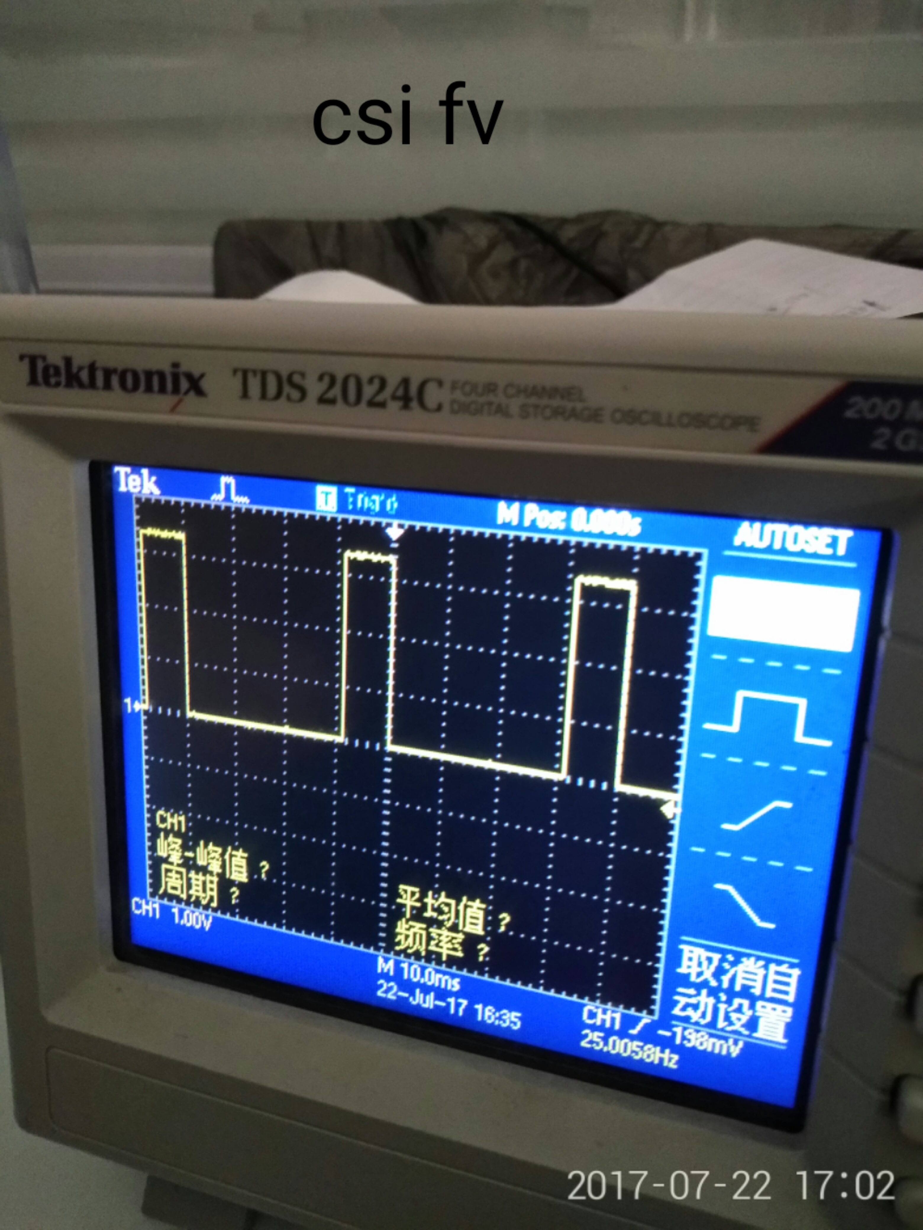
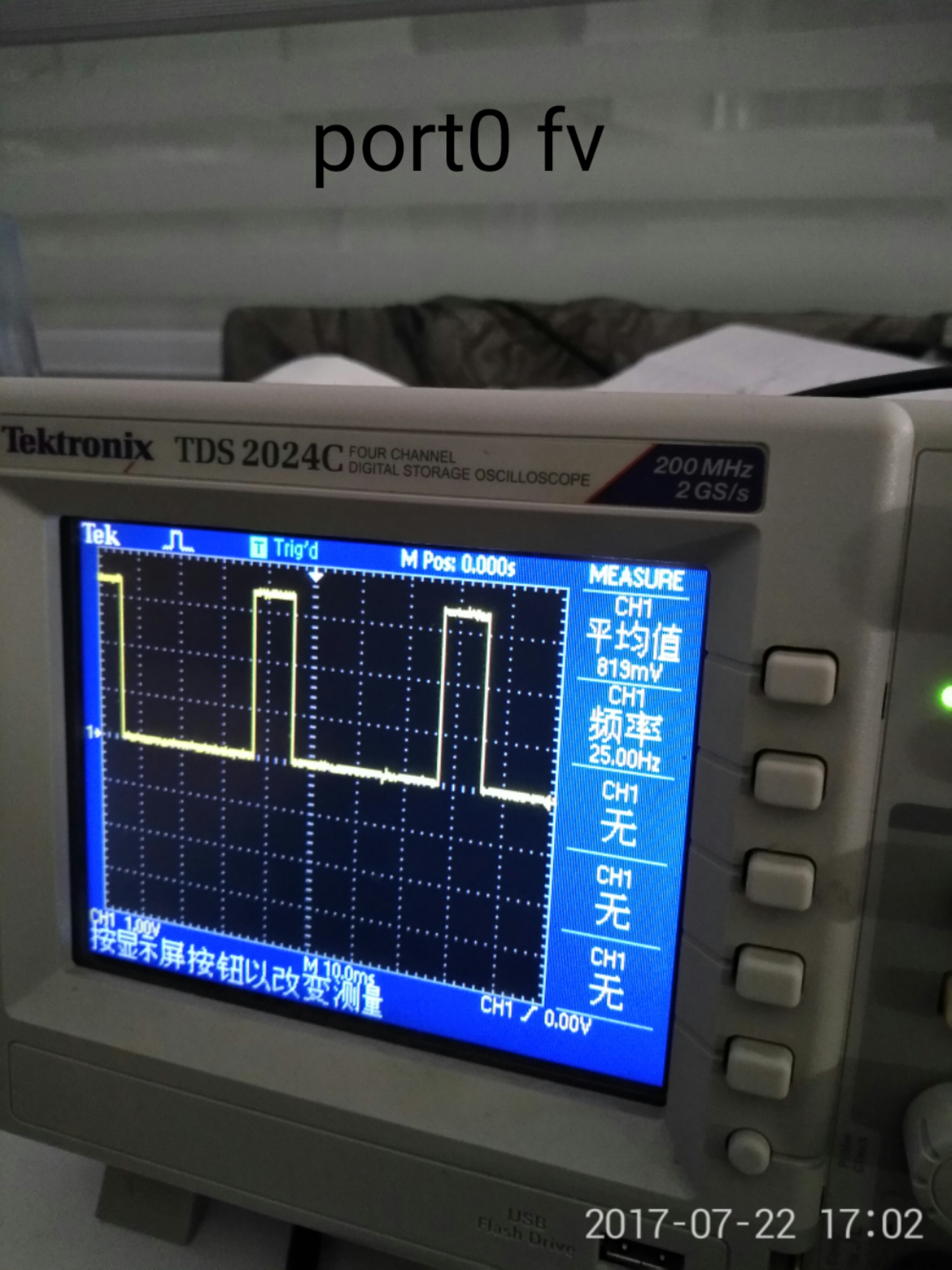
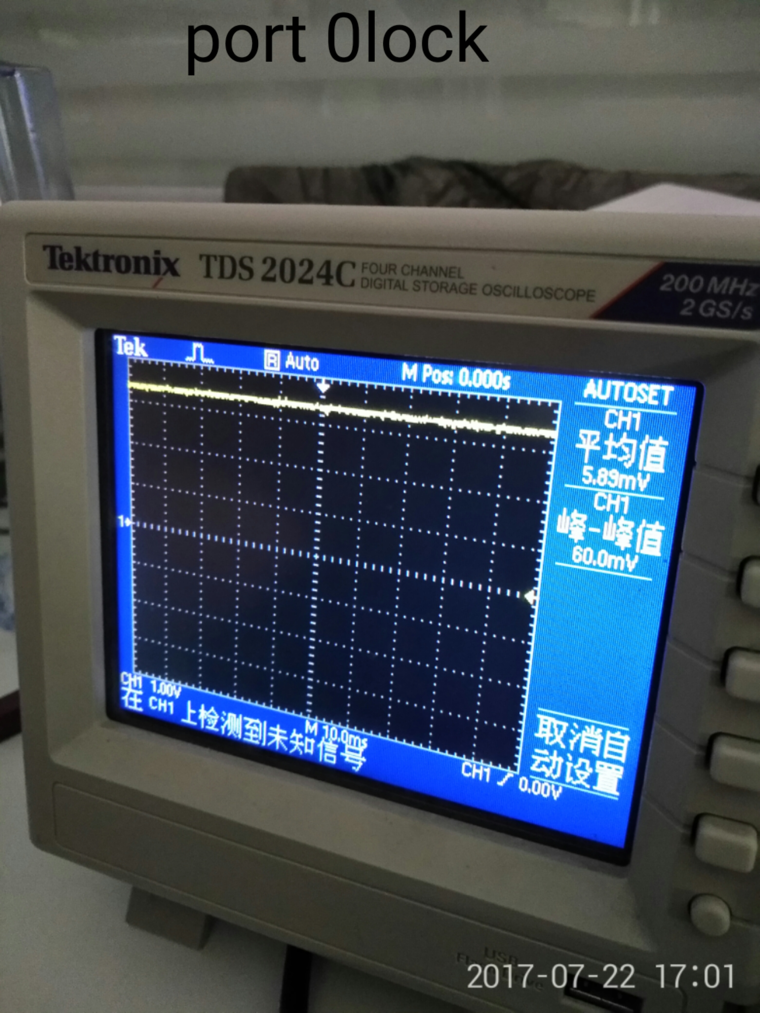
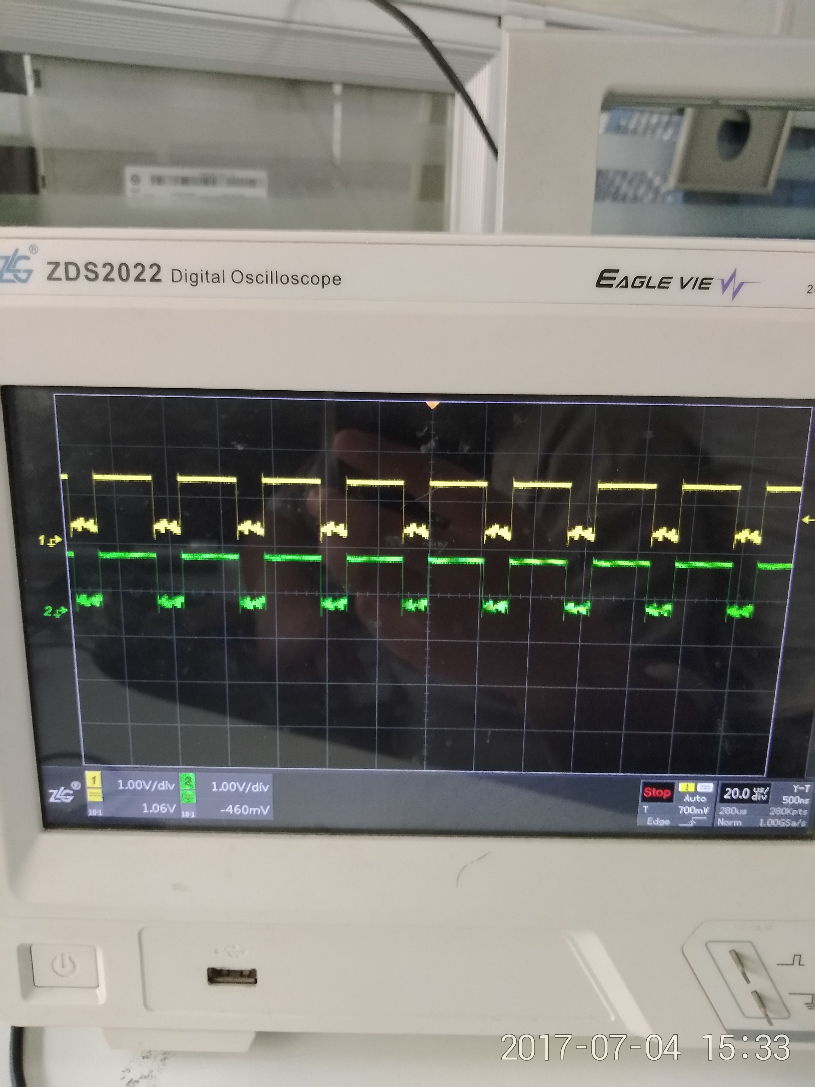
The resulting waveform is as follows:
4.i need to how to set 913 register?
  • Hello,
    We received your question and this has been assigned for an Apps engineer to look at and respond to.
  • hi :

    can you reply me? when i use linux test code mxc-v4l2-tvin -ow 1024 -rotation 1 -oh 768    -f UYVY,dont have enc_counter。

    root@qiyang_6dq:/ # mxc-v4l2-tvin -ow 1024 -rotation 1 -oh 768 -f UYVY
    zhouqun Returning size of 1280x720
    zhouqun:ds964_init_mode
    TV decoder chip is ds964_camerazhouqun :pixelformat == V4L2_STD_PAL

    zhouqun Returning size of 1280x720
    driver=mxc_vout, card=DISP4 FG, bus=, version=0x00000000, capabilities=0x04000002
    fmt RGB565: fourcc = 0x50424752
    fmt BGR24: fourcc = 0x33524742
    fmt RGB24: fourcc = 0x33424752
    fmt RGB32: fourcc = 0x34424752
    fmt BGR32: fourcc = 0x34524742
    fmt NV12: fourcimx-ipuv3 imx-ipuv3.0: init channel = 15
    c = 0x3231564e
    fmt UYVY: fourcc imx-ipuv3 imx-ipuv3.0: initializing idma ch 0 @ d9900000
    = 0x59565955
    fmt YUYV: fourcc = imx-ipuv3 imx-ipuv3.0: ch 0 word 0 - 00000000 00000000 00000000 E0001800 000B3C9F
    0x56595559
    fmt YUV422 planar: foimx-ipuv3 imx-ipuv3.0: ch 0 word 1 - 04A00000 00940000 0147C000 00027FC0 00000000
    urcc = 0x50323234
    fmt YUV444: foimx-ipuv3 imx-ipuv3.0: PFS 0xa, urcc = 0x34343459
    fmt YUV420: fo
    urcc = 0x32315559
    fmt YVU420: foimx-ipuv3 imx-ipuv3.0: BPP 0x3, urcc = 0x32315659
    fmt TILED NV12
    P: fourcc = 0x50564e54
    fmt TILEDimx-ipuv3 imx-ipuv3.0: NPB 0x1f
    NV12F: fourcc = 0x46564e54
    fmt imx-ipuv3 imx-ipuv3.0: FW 1279, YUV444 planar: fourcc = 0x5034343
    4
    imx-ipuv3 imx-ipuv3.0: FH 719,
    imx-ipuv3 imx-ipuv3.0: EBA0 0x25000000
    imx-ipuv3 imx-ipuv3.0: EBA1 0x25000000
    imx-ipuv3 imx-ipuv3.0: Stride 2559
    imx-ipuv3 imx-ipuv3.0: scan_order 0
    imx-ipuv3 imx-ipuv3.0: uv_stride 0
    imx-ipuv3 imx-ipuv3.0: u_offset 0x0
    imx-ipuv3 imx-ipuv3.0: v_offset 0x0
    imx-ipuv3 imx-ipuv3.0: Width0 0+1,
    imx-ipuv3 imx-ipuv3.0: Width1 0+1,
    imx-ipuv3 imx-ipuv3.0: Width2 0+1,
    imx-ipuv3 imx-ipuv3.0: Width3 0+1,
    imx-ipuv3 imx-ipuv3.0: Offset0 0,
    imx-ipuv3 imx-ipuv3.0: Offset1 0,
    imx-ipuv3 imx-ipuv3.0: Offset2 0,
    imx-ipuv3 imx-ipuv3.0: Offset3 0
    start time = 86485 s, 666650 uszhouqun :pixelformat == V4L2_STD_PAL

    zhouqun :cam->enc_counter == 0
    zhouqun:In MVC:mxc_v4l_dqueue
    ERROR: v4l2 capture: mxc_v4l_dqueue timeout enc_counter 0

  • Hi,

    please refer to DS90UB96X-Q1EVM User's Guide, it has one script for reference in page 22. You can configure every FPD-Link RX port parameters, and CSI port as well respectively.

    regarding the pattern generation, you can refer to the example in d/s as well:

    8.5.6.1 Code Example for Pattern Generator
    #Patgen Fixed Colorbar 1280x720p30
    WriteI2C(0x32,0x01) # CSI0 sel and CSI0 enable
    WriteI2C(0x33,0x01)
    WriteI2C(0xB0,0x00) # Indirect Pattern Gen Registers
    49
    DS90UB964-Q1
    www.ti.com SNLS500 –JULY 2016
    Product Folder Links: DS90UB964-Q1
    Copyright © 2016, Texas Instruments Incorporated Submit Documentation Feedback
    WriteI2C(0xB1,0x01) # PGEN_CTL
    WriteI2C(0xB2,0x01)
    WriteI2C(0xB1,0x02) # PGEN_CFG
    WriteI2C(0xB2,0x33)
    WriteI2C(0xB1,0x03) # PGEN_CSI_DI
    WriteI2C(0xB2,0x24)
    WriteI2C(0xB1,0x04) # PGEN_LINE_SIZE1
    WriteI2C(0xB2,0x0F)
    WriteI2C(0xB1,0x05) # PGEN_LINE_SIZE0
    WriteI2C(0xB2,0x00)
    WriteI2C(0xB1,0x06) # PGEN_BAR_SIZE1
    WriteI2C(0xB2,0x01)
    WriteI2C(0xB1,0x07) # PGEN_BAR_SIZE0
    WriteI2C(0xB2,0xE0)
    WriteI2C(0xB1,0x08) # PGEN_ACT_LPF1
    WriteI2C(0xB2,0x02)
    WriteI2C(0xB1,0x09) # PGEN_ACT_LPF0
    WriteI2C(0xB2,0xD0)
    WriteI2C(0xB1,0x0A) # PGEN_TOT_LPF1
    WriteI2C(0xB2,0x04)
    WriteI2C(0xB1,0x0B) # PGEN_TOT_LPF0
    WriteI2C(0xB2,0x1A)
    WriteI2C(0xB1,0x0C) # PGEN_LINE_PD1
    WriteI2C(0xB2,0x0C)
    WriteI2C(0xB1,0x0D) # PGEN_LINE_PD0
    WriteI2C(0xB2,0x67)
    WriteI2C(0xB1,0x0E) # PGEN_VBP
    WriteI2C(0xB2,0x21)
    WriteI2C(0xB1,0x0F) # PGEN_VFP
    WriteI2C(0xB2,0x0A)

    best rgds,

    Steven

  • 你好:
    我是按照datasheet配置的Pattern Generator, 测试之后输出的波形如之前的示波器显示, 请问这个波形是否正确?
    目前遇到的问题是我这边主设备没有解析到数据, 是哪里有问题, 帮忙分析一下, 谢谢!!
  • Yes, it is regular output transition between LP and HS. You can check the error report in the processor side. which processor is used here?

    best regards,
    Steven
  • Hi Junqiang Shi:
    We used NXP imx6q sabresd here, there‘s some problem. Do you have any experience on this processor?
    Have the DS90UB964-Q1 used on this processor before ?
  • Sure, we have many successful cases for the link debug between UB964 and imx6q.

    best rgds,
    Steven
  • Hi Junqiang Shi:

      Q1 :In Pattern Generator mode,Now i have Parsed the data,But i Configured with 8 colors bars,now only two colors ,The following figure is my generated image, is it right?

     Q2:In bist mode ,Is not as long as the configuration ds90ub964 0xb3 enable bist mode can open the 913 bist mode?the following configuration is correct?

    ret = ds964_read_reg(ds964_sensor_data.i2c_client,0x57);

    printk("bist start  err num == %d\n",ret);

    ds964_write_reg(ds964_sensor_data.i2c_client,0x10,0xA1);

    ds964_write_reg(ds964_sensor_data.i2c_client,0x11,0x81);

           ds964_write_reg(ds964_sensor_data.i2c_client,0x4c,0x01);

    ds964_write_reg(ds964_sensor_data.i2c_client,0x58,0x58);

    ds964_write_reg(ds964_sensor_data.i2c_client,0xb3,0x05);

    mdelay(100000);

    ds964_write_reg(ds964_sensor_data.i2c_client,0xb3,0x00);

    ret = ds964_read_reg(ds964_sensor_data.i2c_client,0x57);

    printk("bist end err num == %d\n",ret);

    Q3:Normal mode, fv, lv signal is present but the output is monochrome, no normal display preview, waveform and display as shown below.

  • Hi Junqiang Shi :
    please help me reply this question ,thank you very much!
  • Hi, please help refer to TI's DS90UB96X-Q1EVM User's Guide, which has one example script for reference.
    To configure UB964, you need configure FPD-Link (based on port selection to configure each port), and CSI (also you should select either of the two CSI ports before you configure them).
    for your questions:
    1. The color display is not correct, you can check the simple pattern gen. firstly to check whether the link between UB964 and i.MX6 is correct or not;
    2. In the BIST mode, you can set the register 0xB3;
    3. regarding FV and LV, it seems the polarity is NOT same as the default setting of UB964. please check register 0x7C for the correct setting.

    regards,
    Steven