This thread has been locked.

If you have a related question, please click the "Ask a related question" button in the top right corner. The newly created question will be automatically linked to this question.

TPS65982: Asking for the TPS65982 VBUS cap design

Part Number: TPS65982

Hi Team,
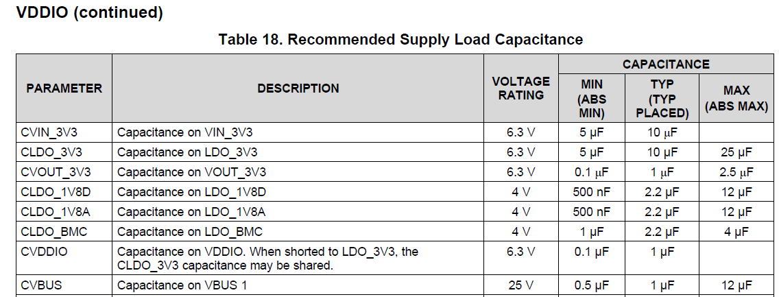
Customer mass production NB design 0.47uF*4 on the VBUS.
TI TPS65982 EVM uses 0.01uF*4 and one 1uF cap on the VBUS.

Is that ok to use 0.47uF on the VBUS? due to it is the mass production project, customer cannot change the schematic and layout. If four 0.47uF is not suggested, could you suggest the four capacitor value to cover this case? Any concern for this cap 0.47uF design?


Thanks,
SHH

  • Hi SHH,

    The capacitance on VBUS pin with an empty unused receptance should be no greater than 10uF to protect legacy USB sources that aren't designed to handle large inrush capcaitnace(like A-to-C cable connections).

    As for the recommend supply load capcitance design, Table 18 in the datasheet spces the absolute minimum capcaitnacen on VBUS line is 0.5uF. This is the reason why the EVM primarily uses the 1uF capacitancen design(typical). The other 4 high frequency noise 10nF capacitors are used to minimize noise.

    It is recommened to change one of the capacitor value to be within the CVBUS range.

    Regards,

    Jimmy Hua

  • Hi Jimmy,

    Thanks for reply.

    So both 0.47uF*4 or 0.47uf*2+0.1uF*2 design looks good and fit int he table 18.
    Is that right?

    If not, any side effect for 0.47uF*4 or 0.47uf*2+0.1uF*2 design?


    Thanks,
    SHH

  • Hi SHH,

    One thing that I would be concerned in the customer's mass production design is that the 0.47uf*4 are still under the absolute minimum requirement for VBUS capcaitance as suggested in the datasheet. If you take into account derating as a result of loading, those capacitance values might be even lower. The reason why the EVM is okay is because it uses the main 1uF typical loading capacitance.

    Regards,
    Jimmy Hua
  • Hi Jimmy,
    This project was transfer to me recently. I do not join the previous review with customer.
    So, customer cannot change the schematic and layout due to mass production at this moment. for the new project, I will suggest them to follow the EVM schematic. However, customer now is focus on how to compensate the mass production NB design.

    Questions:
    1. If only four cap place to place the cap, will 1uF+0.01uF*3 be better for the design? any suggestions?
    2. What will be happen if the cap is under the min value? customer may has concenr for the mass production NB.

    Thanks,
    SHH


    Thanks,
    SHH

  • Hi SHH,

    Just to clarify, there is no issue with using the 0.47uF * 4 design as long as you take into account derating at higher voltage and current. It's to be expected that the capacitors would derate the most under 20V/3A contract. The CVBUS minimum spec is for total capacitance on that line. So if the 0.47uF * 4 that is on the customer's design has a total capacitance that is at least greater than 0.5uF minimum spec after derating, then there should not be a problem.

    The reason why I insist on using 1uF is that it gives more leeway for design.

    Regards,
    Jimmy Hua